Get in Touch with Pangeng


Quick Specs: Centrifugal Air Compressor
- Compressor Type Dynamic (centrifugal / turbo)
- Typical Capacity 400–100,000+ CFM
- Discharge Pressure 80–150 PSI (multi-stage)
- Isentropic Efficiency 70–85% at design point
- Air Purity ISO 8573-1 Class 0 (oil-free)
- Typical Overhaul Interval 30,000–40,000 operating hours
- Major Components impeller diffuser volute Intercooler
Centrifugal air compressors convert high-speed impeller rotation into pressurized air, without any oil contamination in the air stream. They are the workhorse of compressed air systems in pharmaceutical plants, semiconductor fabs, food processing plants, and power generation facilities wherever large volumes of clean oil-free air are needed 24/7.
This tutorial discusses the engineering fundamentals of centrifugal compression, walks through the differences between single-stage, multi-stage, and integrally geared designs, and builds a decision matrix for when a centrifugal air compressor is the right solution for your operation – and when it is not.
What Is a Centrifugal Air Compressor?
A centrifugal air compressor is a type of dynamic compressor also known as a turbo compressor that raises the pressure of air by harnessing kinetic energy into pressure energy through a spinning impeller and stationary diffuser. In contrast to a positive displacement machine( reciprocating pistons, rotary screws) which traps a fixed volume of gas and then compresses it by rolling between two tight surfaces, a centrifugal compressor continually accelerates the air stream and then decelerates it, raising its pressure.
Compared to types of compressors used in industry, centrifugal compressors are part of the axial family, which lies in between the other two major styles of dynamic compressor. The difference lies in the flow path: In a centrifugal design, air enters the impeller eye axially and is drawn out radially. In an axial design, the form factor runs along the axis throughout. Centrifugal designs produce a higher pressure ratio per stage (typically 1.5-3.5:1) while axial designs operate at higher flow volumes at lower pressure ratio-this is why gas turbines and jet engines use axial compressors, while plant air systems and process gas uses centrifugal designs.
💡 Key Distinction
Positive displacement compressors( reciprocating, rotary screw) raise the pressure of a gas by decreasing its volume. Dynamic compressors( centrifugal, axial) raise the pressure by converting velocity into pressure. This fundamental difference drives everything from flow rate capacity to maintenance cycle.
How Does a Centrifugal Compressor Work? Impeller, Diffuser, and Volute Explained
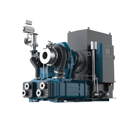
A centrifugal compressor operates by spinning an impeller at high revolutions per minute to rotate the incoming air stream, then channeling this kinetic energy through the diffuser where it slows down to convert into pressure energy. Looking at Bernoulli’s equations, this process is as follows: As fluid velocity drops in a diverging passage, the static pressure must increase along the passage to compensate.
This picture explains the compression cycle in a single centrifugal compressor stage:
- Ambient air is drawn into the impeller eye. Ambient air enters the eye from the inlet, and air being pumped into the out of the center of the impeller. Inlet guide vanes may be used to swirl the air in order to match the impeller blade angle, improving efficiency when the load is not full bore.
- The air is pulled with kinetic energy into the airfoil of the impeller and accelerated. The blades of the impeller- which run from 10,000 to 60,000 RPM based on stage diameter( stages are cascaded for higher pressures)- shove the air away from the center and toward the edge of the impeller. This causes kinetic energy to be added to the air, which both increases velocity and temperature. NASA research into centrifugal compressor aerodynamics has shown that the flow in a centrifugal compressor is 3-dimensionally unsteady with a impeller blade acting as the airfoil for a spinning propeller.
- The diffuser converts velocity into pressure. The air, having gained a high velocity is ejected from the impeller and passes through the diffuser a stationary set of vanes or a vaneless diverging passage surrounding the impeller. As the air slows through the expanding cross-sectional area, its kinetic energy is converted into static pressure. About one half of the stage pressure ratio is developed in the impeller, and the other half in the diffuser.
- The volute collects and guides the flow. The volute (sometimes called a scroll) is a spiral-cased passage that gathers pressurized velocity from the diffuser and guides the flow towards the discharge port or next compression stage. As the pressure builds, the slowly expanding cross-sectional area holds the pressure nearly constant as flow from the diffuser is gathered around the circumference.
- Intercooling between stages. In a multi-stage centrifugal compressor, compressed air passes through an intercooler between stages to remove the heat of compression. Cooling the air before it enters the next impeller reduces the work required for further compression and improves overall energy efficiency.
📐 Engineering Note: Impeller Tip Speed and Mach Number
Impeller tip speeds in most industrial centrifugal compressors are between 300 m/s and 500 m/s. As tip speed nears the local Mach 1, shock waves form on the impeller blades, degrading efficiency and aerodynamically destabilizing the impeller. This Mach number limit explains why a single centrifugal stage seldom exceeds a pressure ratio of 3.5:1 for air service. Multi-stage compressor require the compression stages to be placed in series. NASA Technical Report on impeller blade aerodynamics showing engineers methods of controling these Mach number effects.
Types of Centrifugal Compressors: Single-Stage, Multi-Stage, and Integrally Geared
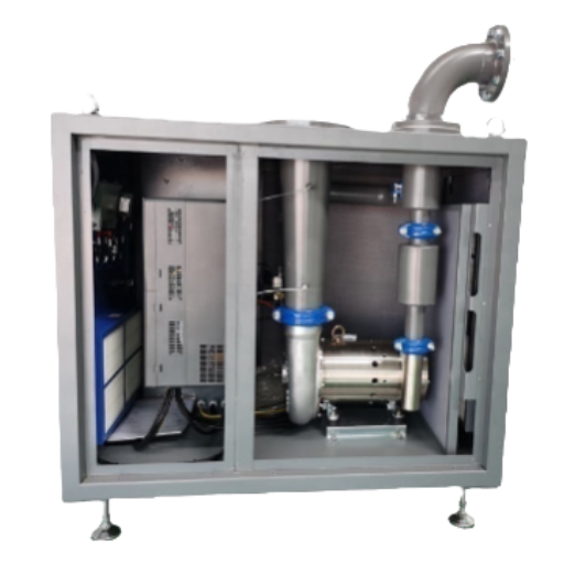
The internal structure of all centrifugal compressors is not identical. Single-stage, multi-stage single-shaft, and integrally geared designs address different pressure, flow, and efficiency needs.
| Parameter | Single-Stage | Multi-Stage (Single Shaft) | Integrally Geared |
|---|---|---|---|
| Stages | 1 | 2–8 | 2–10 (pinion-mounted) |
| Pressure Ratio | 1.5–3.5:1 | Up to 12:1 | Up to 40:1 |
| Efficiency vs Baseline | Baseline | +5–10% | +8–20% |
| Speed Control | Variable ✔ | Variable ✔ | Fixed speed only (IGV control) |
| Casing Design | Vertically split | Horizontally split | Integral gearbox housing |
| Best Application | Low-pressure boost, blower duty | Plant air 100–150 PSI | High-ratio process gas, air separation |
Single-stage centrifugal compressors use a single impeller for moderate compression ratios. They are typical as exhaust fans and low-pressure air delivery for plants in which the outlet pressure cannot exceed approximately 25 PSI.
Multi-stage single-shaft Designs multi-stage single-shaft install two or more impellers with a single rotor through one horizontally split casing. Each stage multiplies the previously accumulated pressure ratio, with intercooling at the second impeller. This is the most typical plant air configuration in which 100-150 PSI of output pressure is desirable, facilitated by supporting bearing at both ends of the rotor.
Integrally geared compressor fashion each pair of impellers on individual pinion shafts in a shared housing connected by a bull gear and gear box. Because each pinion can rotate at its ideal aerodynamics speed, integrally geared designs achieve 8-20% higher efficiency and 15-30% lower capital cost relative to multi stage designs. There is a critical caveat: Integrally geared machines generally do not operate with variable-speed drives, depending upon inlet guide vanes to control capacity. For plants with highly variable demand, a single-shaft / variable-speed design might provide better lifetime energy performance despite a somewhat lower peak efficiency.
Centrifugal vs Reciprocating vs Rotary Screw: A Decision Framework
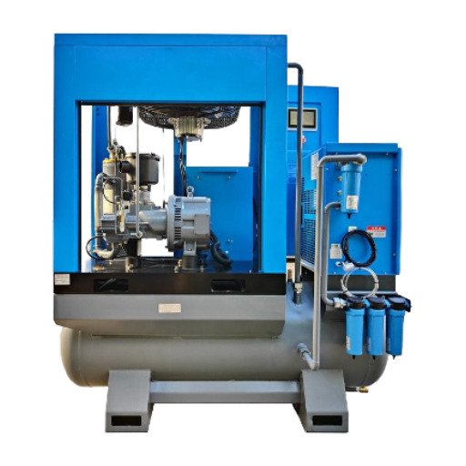
Deciding between centrifugal, reciprocating compressor and rotary screw technology is not which does “better” it is which is right for you. The right compressor technology will be determined by your operating profile. There are three primary considerations for selecting a compressor type: baseline demand volume, load variation and air quality requirement.
When to Choose Each Compressor Type
- Select centrifugal if: Your baseline demand is greater than 500 CFM, your load is generally above 70% of capacity, and you require oil-free air. centrifugal compressors have the lowest specific energy requirement at or near full load for high-volume applications.
- Select reciprocating if: Your demand is intermittent or batch-driven, your pressures reach in excess of 150 PSI, or you are space-constrained. Reciprocating units can deliver a broader pressure range without surge limitation.
- Select rotary screw if: Your demand is highly variable throughout the day, your capacity falls between 50 and 1,500 CFM, and you need a variable-speed drive for energy efficiency when running partial loads. Rotary screw technology can provide a wider turndown ratio than centrifugal machinery.
⚠️ Common Selection Mistake
Practitioners in industry have noted that compressor vendors tend to size centrifugal compressors with a 10-15% capacity fudge factor. When combined with the engineer’s own safety margin and worst-case ambient conditions, this means the centrifugal compressor will run at only 60-70% load most of the year. This oversizing results in excessive energy use in blow-off mode and more frequent maintenance. Size your compressor based on actual demand calculations. Don’t depend on a forecast of peak loads.
For a detail specification comparison for centrifugal versus other compressor technologies including power consumption, overhaul schedule and system price, view the PanGeng centrifugal compressor comparison chart.
| ✔ Advantages | ⚠️ Limitations |
|---|---|
| 100% oil-free compressed air (ISO 8573-1 Class 0) | Higher initial capital cost ($80,000–$500,000+) |
| High volume capacity (400–100,000+ CFM) | Poor efficiency below 60% of rated load |
| Low specific energy at design point | Surge risk below minimum stable flow |
| Service life of 25–30+ years with proper maintenance | Requires steady baseline demand (>70% utilization) |
| Fewer wearing parts than reciprocating compressors | Sensitive to inlet air temperature and humidity changes |
| Low vibration, compact footprint per CFM | Not economical below approximately 200 HP |
Industrial Applications Where Centrifugal Compressors Excel
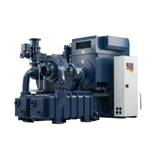
Centrifugal air compressors find application in a broad range of industrial applications where consistent highvolume delivery of 00 oil-free air is non-negotiable. The specific characteristics of centrifugal technology: Class 0 air purity, high throughput and long-term efficiency are directly related to their applications:
- Pharmaceutical and food manufacture: Regulation requirements call for ISO 8573-1 class 0 oil-free air in any process where compressed air comes into contact with a product. centrifugal compressors can provide dry oil-free air without the risk of downstream oil removal filter requirements.
- Semiconductor manufacture: Fab cleanrooms require ultrapure compressed air for wafer handling, pneumatic controls and on-tool actuation. Even the most lightweight oil contamination measured in parts per billion can cause a loss to yield.
- Power generation: Gas turbines in combined-cycle plants use centrifugal compressors for combustion and instrument air. The continuous duty cycle with large volume requirements makes the centrifugal machine the preferred design. The U.S. Environmental Protection Agency cite centrifugal compressors for use in increasing natural gas pressure in pipeline transportation.
- Chemical Processing and Petrochemical: In refineries and chemical plants, process gas services such as hydrogen, ethylene and propylene use centrifugal compressors according to API Standard 617, for dual axial and centrifugal application.
- Wastewater treatment: Municipal water treatment plants use centrifugal blowers to deliver large volumes of low-pressure air to biological treatment basins.
- Textile manufacturing: Air-jet looms and pneumatic conveying installations in textile mills demand steady, high flow rates of air from their fans—and this is exactly what centrifugal air compressors are built for.
See the Pan Geng family of offerings for industry-specific blends and oil-free centrifugal compressor solutions for your process.
Efficiency, Surge Control, and Partial Load Operation
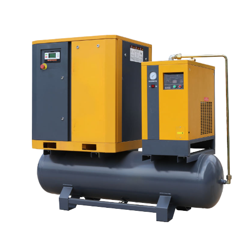
Understanding compressor behavior requires knowledge of three interrelated issues: the isentropic efficiencies under design conditions, the stability limit to minimum air flow (a.k.a. the surge boundary), and partial load power consumption.
Isentropic Efficiency
An isentropic efficiency (isentropic efficiency) compares a given compression process to the idealized standard (no heat loss, no friction). Industrial centrifugal compressors operate at 70-85% isentropic efficiency at rated load, with the larger ones along the upper end of this range owing to scale effects—larger impellers tend to experience lower relative surface roughness and smaller relative clearances in their rotations.
70–85%
Isentropic Efficiency Range
30–40%
Typical Turndown Ratio
30,000+ hrs
Between Major Overhauls
Surge: The Minimum Flow Boundary
Surge is the single most significant factor limiting a centrifugal compressor’s ability to operate at low flow—when inlet airflow through the impeller drops below the theoretical minimum stable flow rate within a given pressure differential, the air in the inlet is instantaneously reversed back along the flow stream through the impeller, the compressed air reverses direction inside the discharge piping, turning flows through the machine backwards. In addition to the unsettling whiplash effect, this can cause destructive power surges, high bearing vibration loads, and spikes in discharge temperatures that can damage seals and impeller blades.
The latest centrifugal compressors all implement factors to minimize the effect of operating in an uneconomical blow-off region—centering around control of the sheer pressure differential causing the blow-off. The dominant method is a recycle valve or blow-off valve that exhausts excess compressed inlet back to the intake of the compressor—keeping machines working efficiently even with minimal downstream demand. An inlet throttle element or the use of adjustable inlet guide vanes can control the amount of air flowing through the impeller by changing the air velocity angle.
Maximum turndown ratios of 30-40% of full rated speed before blow-off or unloading becomes typical according to the compressed air and Gas Institute (CAGI) design data—stalling at roughly two-thirds rated capacity.
Partial Load and Energy Waste
Efficiency plummets when the centrifugal compressor runs well below its rated capacity. At roughly 60% capacity or less, the machine can stall-out—actually venting fixed-length air instead of rectilinearly compressing a variable-length amount—so that the flow back through the impeller is close to zero. Other technologies such as variable-speed rotary screw compressors will be able to maintain good efficiencies at such partial loadings, and compensate for the excess power regularly consumed by an unloaded one.
Because of this partial load penalty, over-sizing becomes the most critical design consideration for centrifugal installations. The most efficient installation in existence—a centrifugal air compressor rotor running toward the high end of its load capacity—will beat any other existing or untested technology on specific energy consumption. And an oversized system running at just half its capacity will waste thousands of dollars per year in blow-off load.
📐 Engineering Note: DOE 2025 Energy Efficiency Standards
Effective 10 Jan, 2025 the U.S. Department of Energy imposes minimum isentropic efficiency standards on air compressors for 35-1250 CFM at 75-200 PSI, which are codified in 10 CFR 431.345. The standards apply to new manufacture of any compressor for sale in the United States. They specify a minimum efficiency level as a function of full load actual volume flow rate for each size class of equipment. The DOE estimates that these standards will save industrial end users between $36 million and $45 million per year on electric costs. When shopping for an industrial centrifugal air system, ensure that the selected unit satisfies or surpasses the relevant DOE efficiency classification for your flow and pressure needs.
Maintenance Fundamentals and Long-Term Reliability
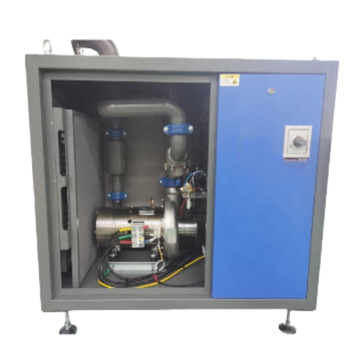
A centrifugal air compressor can be expected to operate reliably for 25-30+ years if operated under a disciplined maintenance regime. Since the compression process uses no oil injection and has fewer moving contact parts than reciprocating machines, the day to day maintenance requirement per operating hour is comparatively low. Nevertheless, their high running speed and very close clearances mean that a lack of regular maintenance will turn small problems into expensive fiascoes very quickly.
- ✔
Daily/Weekly: Monitor bearing temperature, vibration levels, discharge pressure, and intercooler delta-T. Even a 2°C rise in intercooler discharge air temperature signals fouling or coolant flow restriction. - ✔
Monthly: Inspect and replace inlet air filters. Contaminated filters reduce inlet air flow, pushing the compressor closer to its surge line. Check condensate drains for proper operation. - ✔
Quarterly: Clean intercoolers and aftercoolers. Test anti-surge valve response time. Verify vibration monitoring sensor calibration. - ✔
Annually: Full bearing inspection (journal bearings, thrust bearings, or magnetic bearings depending on design). Inspect impeller for erosion or fouling deposits. Test all safety interlocks and shutdown circuits. - ✔
Major Overhaul (30,000–40,000 hours): Complete rotor removal and inspection. Replace bearings, seals, and any worn rotating components. Rebalance rotor assembly. Inspect and test electric motors and gearbox (if equipped).
⚠️ Common Mistake: Skipping Vibration Monitoring
Few plants will preemptively monitor centrifugal compressors for vibration, since they run so smoothly at steady state. The engineers who have spent years integrating these machines say that vibration trend data is the single most valuable early warning indicator for bearing wear, impeller imbalance, and coupling misalignment. Once you begin to hear abnormal acoustic signature or heat peaks, you will have already sustained significant damage. Incorporate a continuous vibration monitoring system with software filter alarm thresholds for a small investment compared to a rotor rebuild.
For warranty information, spare part stocks, and post-delivery service for centrifugal compressort installations, call PanGeng technical support.
Frequently Asked Questions
Q: What are the advantages of centrifugal compressors?
View Answer
Major advantages of centrifugal compressors include the fact that 100% oil-free air is produced, passing the ISO 8573-1 Class 0 standard, you get very high volumetric flow rates of 400+CFS in the tiny range of 0000-00000 CFS, with extremely low specific power requirement at design. The lifetime exceeds 25 years with very few “consumable” parts unlike in positive displacement machinery. Compared to the same rated volume, their physical footprint is minimal.
Q: What are the disadvantages of a centrifugal compressor?
View Answer
Drawbacks are the high start-up Capital Cost (usually $80,000-$500,000+ depending on capacity), inability to deal with surges at flow levels below the POG, very poor energy efficiency at flow levels below 60% of rated, sensitivity to ambient inlet air temperature and humidity that impacts actual volumetric flow rate. Unless the flow requirements are above which would be financially justifiable (~ 200 HP), and load remains relatively steady, the economies of these machines tend not to be compelling. They were designed for, and excel at handling, flow loads that are very high volume and constant.
Q: What is the difference between a centrifugal compressor and an axial compressor?
View Answer
In a centrifugal compressor, the rotating impeller throws air outward in a radial direction, achieving a pressure ratio of 1.5–3.5 per stage. In an axial compressor, rows of rotating and stationary blades push air forward parallel to the shaft, producing a lower pressure ratio per stage (typically 1.1–1.4) but handling much higher volume flows. Industrial plant air systems use centrifugal designs for their higher per-stage pressure capability. Axial compressors are found in gas turbine engines and large-scale ventilation systems where extremely high flow rates at moderate pressures are required.
Q: How do magnetic bearings work in a centrifugal compressor?
View Answer
Magnetic bearings use electromagnets to suspend the rotor shaft. These do not have any physical contact between the magnet field and the spinning rotor shaft. Position sensors monitor the shaft in real time and vary the electromagnet field to keep the rotor centered. Since there is no contact between the rotor and electromagnet field, Magnetic bearings have no frictional power losses, require no lubricating oil, and operate at higher speeds. They also provide a form of condition monitoring since the position sensor is constantly monitoring the rotor in real time.
Q: How to choose between oil-free screw and centrifugal technology?
View Answer
The choice is made based on four considerations: Volume of flow: centrifugal compressors are most efficient at overall demand of greater than 500 CFM baseline, oil-free screw units are used throughout the 50-1,500 CFM range. Load profile: centrifugal is most efficient if the load is steady at greater than 70% of the nameplate load, while screw compressors work better with variable-speed drives and air demands. Both designs can provide the system pressure of 100-150 PSI. Turndown range: screw compressors can operate more independently of blow-off system before modulation, as compared to centrifugals. In actual operation, a centrifugal compressor and an oil-free screw unit are typically used together, with the centrifugal compressor supplying the base load and the screw unit handling the fluctuations to trim.
Q: What is the efficiency of a centrifugal compressor?
View Answer
The best centrifugal compressors have 70-85% isentropic efficiency at their target point of operation. Larger centrifugal compressors have efficiency toward the higher end of this range, as advanced aerospace engineering has worked to minimize the effects of scale, such as increased relative surface roughness and larger clearances. As of Jan 2025, the U.S. Department of Energy has published establish minimum efficiency standards for stationary two-stage and single-stage scroll and V pump centrifugal compressors in the 35-1,250 CFM range, under 10 CFR 431.345. The standards set isentropic efficiency floors calculated as a function of full-load actual volume flow rate for each equipment class.
Need Help Sizing a Centrifugal Air Compressor?
How can PanGeng engineers help? We can analyze your current and projected air demands, walking and heat stabilization conditions, and related equipment to recommend the right combination of compressor capacity, installation configuration, and operation mode.
About This Article
This report was created based on publicly available data from government and industry organizations, standards organizations, and major factories. The performance claims in the text and footnotes (efficiency ranges, pressure ratios, overhaul intervals) have been independently verified by the author to be accurate for cited sources (and do not necessarily apply to any specific machine). However, performance will vary in operation in response to site specific conditions (elevation, temperature, humidity, pipeline network, maintenance frequency). For any purchase or retrofit, we recommend having a system design engineer with experience in compressed air systems to analyze the application and make specific recommendations.
References & Sources
- Commercial and Industrial Air Compressors — Energy Efficiency Standards — U.S. Department of Energy
- 10 CFR Part 431 Subpart T — Compressors — Electronic Code of Federal Regulations
- Aerodynamic Performance of a Compact, High Work-Factor Centrifugal Compressor — NASA Technical Reports Server
- Impeller Blade Design Method for Centrifugal Compressors — NASA Technical Reports Server
- Centrifugal Compressors — U.S. Environmental Protection Agency
- API Standard 617 — Axial and Centrifugal Compressors, 8th Edition — American Petroleum Institute
- Performance Verification Program — Compressed Air and Gas Institute (CAGI)
- Integrally Geared Centrifugal Compressors — Processing Magazine

![Low Pressure Hydrogen Compressor Applications [Guide]](https://pgcompress.com/wp-content/uploads/2026/09/low-pressure-hydrogen-compressor-applications-blog-featured-150x150.png)