Get in Touch with Pangeng

Oil and Gas Booster Compressor: A Practical Engineering Guide

Contents
show
Engineering Guide
The design basis for a booster compressor project goes beyond discharge pressure alone. The real design basis is a moving envelope of gas composition, suction conditions, flow, stage loading, cooling, separation, control states, and site interfaces. This document details how to arrive at this basis prior to the quoting or approval of a package.
A gas compressor can be used as a booster receives gas downstream of a primary compressor or another pressurized gas source. It reduces the volume of gas to increase the pressure. The required outlet pressure and flow rate define only part of the duty. The inlet pressure, gas temperature, gas type, and pressure and flow requirements assist in evaluating the required compressor work and determining whether the chosen gas compression arrangement can work safely.
This document provides guidance for hydrocarbon gas handling. It isn’t a general air compressor or air booster guide. Other parts of equipment, gas supplies, and protection may vary with the nature of gas, especially if it contains significant amounts of oxygen. A pneumatic or hydraulic gas booster, including equipment described as a nitrogen booster or as pneumatic gas boosters for high pressure gas, may work on a similar principle as a booster, but it doesn’t prove suitability of the equipment for gas and oxygen service.
The machine is used to increase gas pressure after the stream is already compressed; it is not a universal device for any air or nitrogen duty. The volume of a gas varies with pressure and temperature. Equipment marketed for service in the oilfield isn’t always suitable for gas and oxygen service with hydrocarbons.
Define the Booster System Boundary Before Sizing
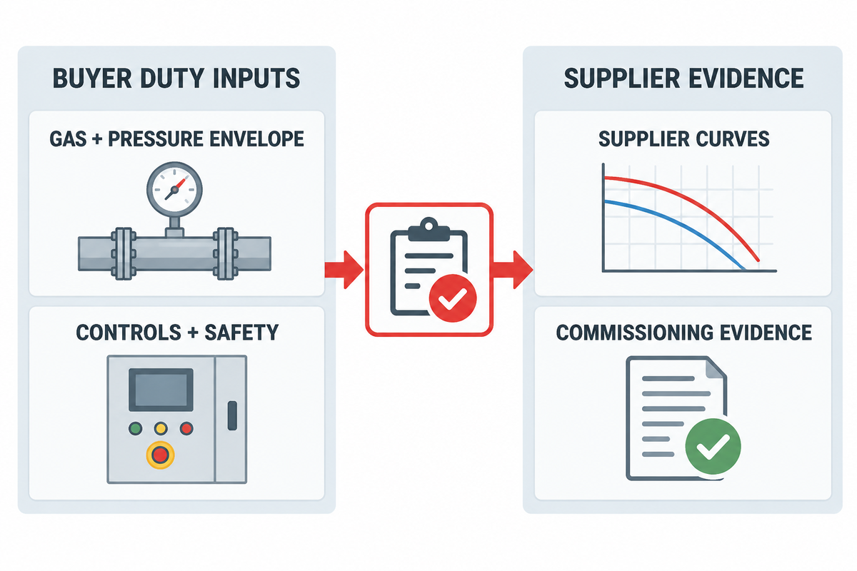
A booster is a secondary compression stage: its suction gas is already above atmospheric pressure and must be raised to a higher delivery pressure. A booster is easy to define, and the package boundary determines the system’s complexity.
The gas system boundary and the evidence required to select a booster also depend on the type of service: pipeline gas transfer, vapor recovery, injection, industrial gas service, or pressure testing. Each use changes the gas system boundary and the evidence needed to choose a booster for your application.
To start, draw the process from the upstream source to downstream user. Include the inlet isolation valve, scrubber or coalescer, compressor stages, interstage coolers and separators, aftercooler, final separator, check valve, discharge isolation, recycle or bypass path, relief devices, vents, drains, and blowdown destination. Add the driver, lubrication systems, cooling utilities, control panel, emergency shutdown signals, gas detection, and hazardous-area interfaces. Include gas detection systems, and state the type and class of the area.
The current API catalog identifies API 618, sixth edition, May 2024, as covering reciprocating compressors plus related lubrication systems, controls, instrumentation, coolers, pulsation suppression, and auxiliaries. API’s digital catalog also lists API Spec 11P, edition 3, for packaged reciprocating compressors in oil and gas production service. A project specification should state which standard and edition governs; neither title is a substitute for the purchased standard or the owner’s requirements.
Start With the Gas and Suction Envelope
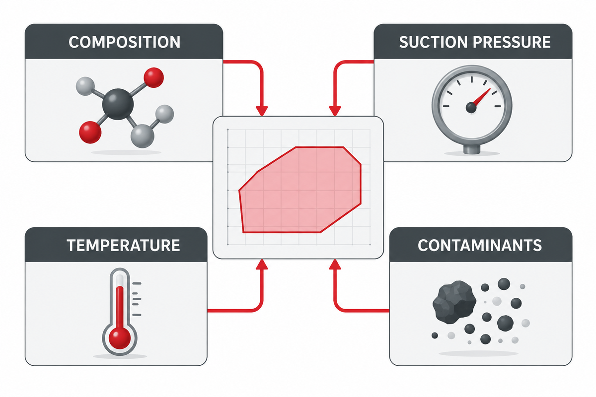
A single “rated” suction pressure conceals the condition which often decides the fate of a package. Record minimum, normal, and maximum suction pressure and temperature, required flow at each case, target discharge pressure, duty cycle, ambient range, and expected field decline or upstream variability.
It should be understood that when dealing with compressibility of a given fluid, absolute pressure must be used to evaluate the compression ratio. The flow reference should always be clear – actual or standard volume, temperature and pressure, and presence or absence of water vapor. A stated flow value with no definition of the conditions isn’t a valid capacity requirement.
The gas analysis should cover molecular weight, compressibility, heat-capacity ratio, water, heavier hydrocarbons, hydrogen sulfide, carbon dioxide, oxygen where relevant, and any component that affects materials, lubrication, condensation, or hazardous-area classification. When composition changes between wells, seasons, batches, or operating modes, state bounded cases rather than an average.
There are different standard and actual gas volumes. Standard volume is different from actual inlet gas volume. Increasing gas pressure changes density and volume; therefore, the gas pressure, reference conditions, and compressibility basis should accompany each flow statement. This is particularly important when a large gas source feeds several compressor systems, or when operators compare driven gas boosters from different suppliers.
Buyer Asset 1: Gas and Suction Envelope Worksheet
Fill in this table first to compare quotations. A blank entry in this table is a technical query, not an innocent omission.
| Input category | Minimum case | Normal case | Maximum case | Owner |
|---|---|---|---|---|
| Suction pressure, absolute | Record | Record | Record | Process |
| Suction temperature | Record | Record | Record | Process |
| Required mass/standard flow | Record | Record | Record | Operations |
| Gas composition and analysis date | Attach | Attach | Attach | Process/QA |
| Water and hydrocarbon dew-point margin | Check | Check | Check | Process |
| Liquid/solid contamination control | Define | Define | Define | Operations |
| Discharge requirement | Record | Record | Record | Downstream user |
| Ambient and cooling condition | Record | Record | Record | Utilities |
| Operating mode and duration | Define | Define | Define | Operations |
Buyer action: Buyers should request that comparisons of quotes not be made when different gas analyses or flows, or different suction cases, are employed.
Liquid protection is part of the duty definition. Southwest Research Institute evaluates separator performance by measuring liquid carryover across a range of inlet conditions. That’s a useful lesson: separator efficiency at one point doesn’t prove performance across changing gas and liquid loads.
Review Pressure Ratio, Staging, and Temperature Together
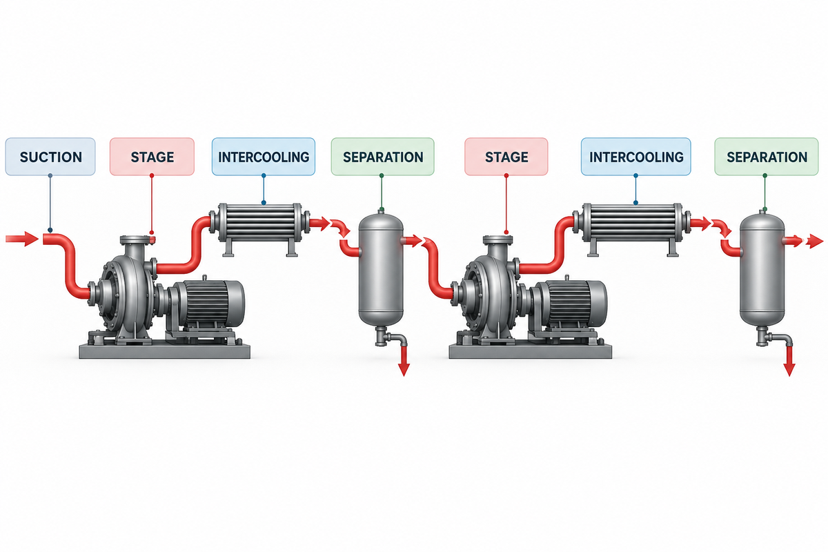
The overall compression ratio is discharge absolute pressure divided by suction absolute pressure. For a multistage machine, the ratio and predicted temperature at each stage should be reviewed at every governing case. Balanced ratios may be a useful starting point, but cooler approach, pressure losses, gas properties, cylinder selection, valve behavior, and capacity control can move the practical split.
The working principle of booster compressors is well known: booster compressors increase the pressure of a gas that has already reached a positive inlet pressure. Once a positive inlet pressure is achieved, manage the resulting pressure increase and heat. The simplicity of this may mislead buyers. A high-pressure compressor must still match the pressure of air or gas at its inlet, the pressure of the gas at its outlet, and the full operating range. Booster compressors work only within the mechanical and thermal limits established for the selected machine.
Ariel notes that higher ratios raise discharge temperature, reduce volumetric efficiency, affect valve events, increase sensitivity to pressure changes, and can increase rod load. Its practical ratio warning is explicitly an application-review trigger. It isn’t a universal limit.
Ask the vendor to show predicted suction and discharge temperature, capacity, absorbed power, volumetric efficiency, rod loads, valve limits, and driver load for each stage and each operating case. Temperature limits should come from the gas and lubricant, sealing materials, valve design, cylinder construction, downstream constraints, and governing specification, not from a general blog.
Buyer Asset 2: Stage Loading Review
| Case | Stage ratio | Discharge temperature | Capacity | Rod/driver load | Valve and control state | Disposition |
|---|---|---|---|---|---|---|
| Minimum suction / required discharge | Vendor value | Vendor value | Vendor value | Vendor value | State | Accept/revise |
| Normal suction / normal flow | Vendor value | Vendor value | Vendor value | Vendor value | State | Accept/revise |
| Maximum suction / turndown | Vendor value | Vendor value | Vendor value | Vendor value | State | Accept/revise |
| Startup, recycle, or unloaded state | Vendor value | Vendor value | Vendor value | Vendor value | State | Accept/revise |
Hidden bottleneck: a thermally acceptable point can still be unacceptable for valves, rod load, pulsation, driver margin, or control stability.
Choose Architecture and Driver by Duty
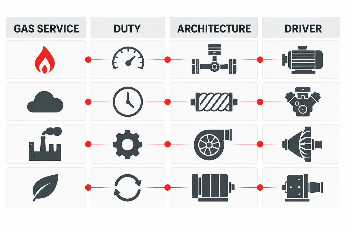
Reciprocating compressors are appealing for higher pressure ratios, variable suction conditions and lower to moderate flows. Screw machines can cover broader continuous flows, and tolerate wet gas better, if the designed separation system and selected design allow it. Centrifugal machines can take larger, more constant flows in an aerodynamic operating map. Diaphragm machines can take high purity or leak sensitive services at low flows and high pressure.
Those are screening directions, not selection rules. Check gas compatibility, leakage tolerance, turndown, maintenance philosophy, starts per hour, pulsations and vibrations, footprint, utilities and the available driver.
Both a reciprocating unit and a rotary compressor can increase pressure, but their constraints on control and maintenance differ. Some services require high-pressure at moderate flows; others prefer continuous transfer. A high-pressure air or gas label, or a claim of efficient gas delivery, cannot replace a review of compressor performance at the stated gas conditions.
A “non-lubricated” cylinder means cylinder lubrication isn’t injected. It does not prove that upstream contaminants, packing leakage, wear debris, corrosion products, or downstream equipment cannot affect gas quality. If cleanliness matters, specify a measurable gas-quality target, sampling point, test method, and acceptance criterion.
For deeper architecture boundaries, compare the diaphragm versus reciprocating compressor guide, the API 618 reciprocating compressor checklist, and the engineered gas compressor package guide. These articles address narrower questions and don’t replace a review of the duty envelope here.
| Architecture | Screening strength | Hidden constraint to verify |
|---|---|---|
| Reciprocating | High ratio and variable-duty flexibility | Valves, rod load, pulsation, packing, liquid protection |
| Screw | Continuous flow and compact packaging | Oil carryover, discharge temperature, efficiency at off-design conditions |
| Centrifugal | Large steady flow | Surge/choke map, gas-property shifts, minimum stable flow |
| Diaphragm | Leak-sensitive or high-purity duty | Flow range, diaphragm life, contamination and monitoring strategy |
Design Controls for a Moving Operating Envelope
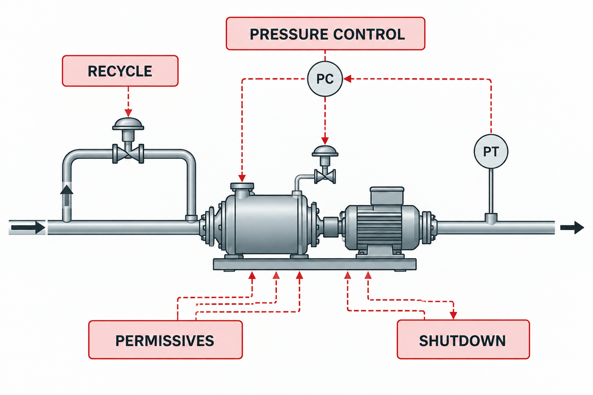
The control narrative should explain what the package does when suction pressure, flow demand, discharge pressure, ambient temperature, cooler performance, or gas composition moves away from normal. Include permitted operating regions, alarm and shutdown regions, and the action that moves the system between them.
Capacity control may use speed control, clearance devices, unloaders, recycle or bypass, and start/stop sequencing. The chosen control sequence must be assessed against driver load, minimum speed, valve behavior, temperature, rod load, pulsation, and mechanical vibration. A process control solution is incomplete without addressing the mechanical response.
Public setpoints shouldn’t be used in projects. Regulations may publish specific triggers for clearly defined facilities, but the site’s approved cause-and-effect matrix, relief study, hazardous area design, and jurisdiction dictate what the package should do. Use the applicable compressor standard and edition as a documented design input; the API standards catalog identifies the current scope and edition of relevant API documents.
Buyer Asset 3: Moving Envelope Control Map
| Condition | Detect | Control response | Protective response | Evidence required |
|---|---|---|---|---|
| Falling suction pressure | Pressure and rate of change | Reduce capacity within approved map | Low-low trip if boundary is crossed | Case curve and setpoint basis |
| High interstage temperature | Stage temperature | Unload/reduce speed as approved | Trip at approved limit | Material and gas basis |
| High separator level | Independent level protection | Drain if available | Stop before liquid ingress | Cause-and-effect test |
| Discharge restriction | Pressure and valve status | Recycle/unload if approved | Trip and relief protection | Relief and transient study |
| Gas detection / ESD | Site safety system | Fail-safe valve action | Isolate, stop, depressurize as designed | ESD test record |
Close Cooling, Separation, and Safety Interfaces
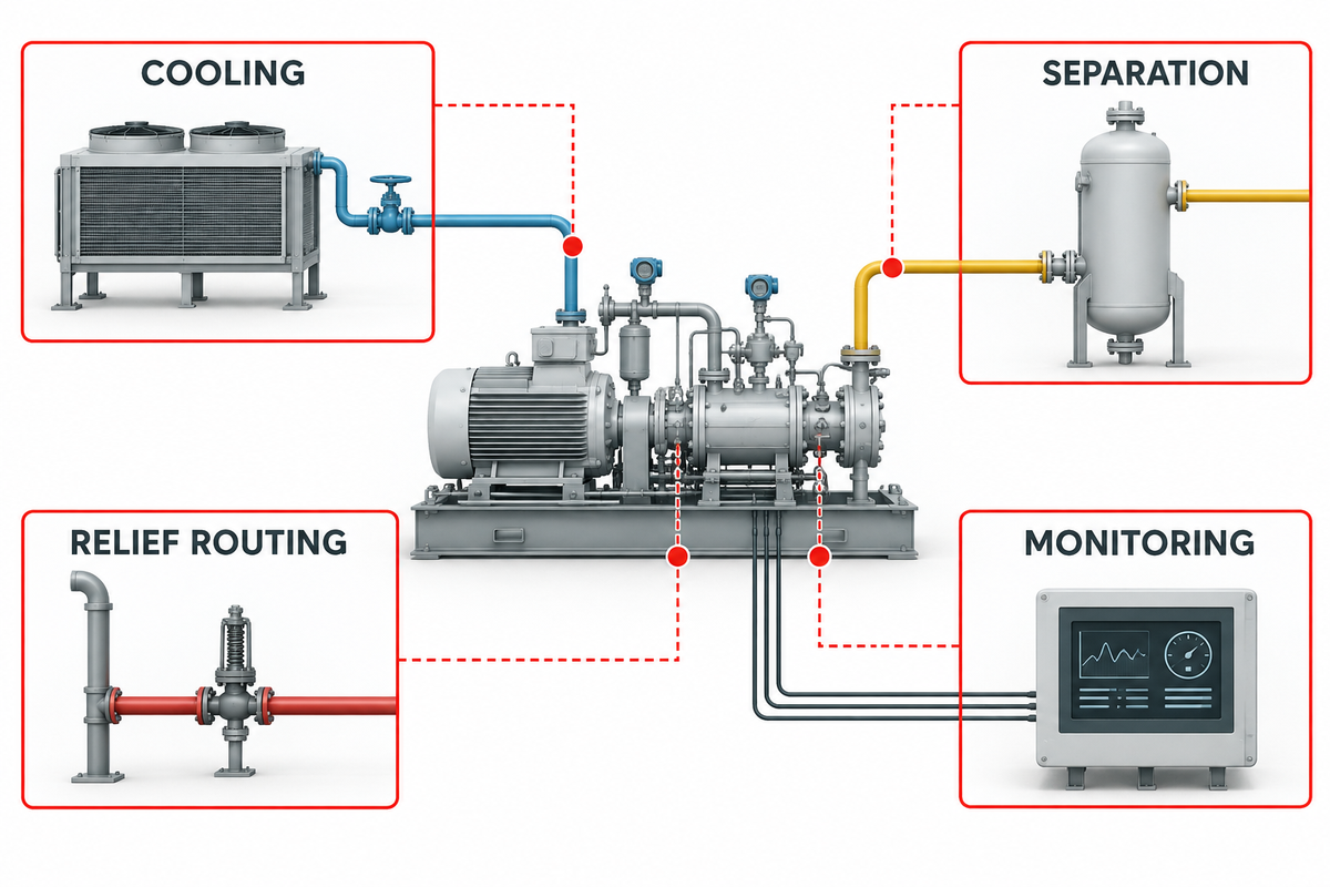
Intercooling can reduce the inlet temperature to the next stage and lessen compression work, but can also condense water and hydrocarbons. Each cooler should be assessed with respect to the phase downstream, the separator duty, the integrity and reliability of the drains, level protection, and the route of disposal.
A compressor handles gas, not gas or liquid generally. Cooling can turn part of the gas stream into liquid, so the system must separate that liquid before it reaches the next stage. This is why a promise to boost gas pressure is incomplete without drains, level protection, and a defined response to carryover.
Define allowable pressure losses through suction equipment and coolers at clean and fouled conditions. Confirm winterization, freeze protection, ambient design, and cooling-medium limits. Address what happens in the absence of cooling. A separator nameplate alone doesn’t prove droplet removal across the full operating envelope.
Shutdown and blowdown deserve their own operating case. EPA distinguishes operational and maintenance shutdowns, emergency shutdowns, and ESD testing; isolated gas may be vented, flared, or handled by a recovery system depending on the facility. Define isolation volume, destination, ignition control, permitted duration, restart conditions, and reporting responsibility under the applicable rules.
Safety interfaces are not accessories around the compressor. They determine whether the package can enter, remain in, and leave each operating state without transferring an unmanaged hazard to the plant.
Commission Against Evidence, Not Presence
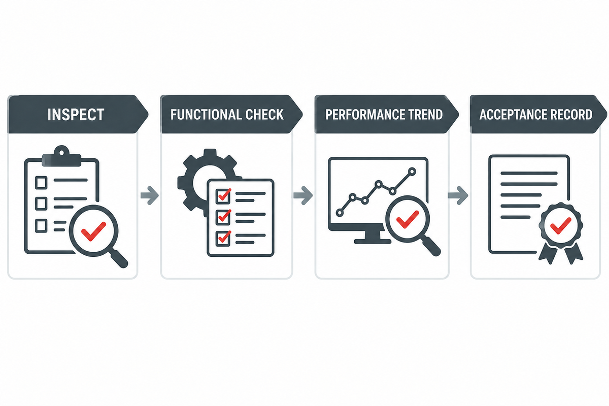
Arrival on site doesn’t prove the package meets the duty. Mechanical completion includes verified P&IDs, valve lineups, relief devices, vents, drains, cleanliness, lubrication and cooling systems, electrical checks, instrument calibration, rotation checks, leak tests, and permissive simulation.
Ariel’s startup checklist includes pressure and temperature records, piping and instrumentation verification, relief protection, and attention to abnormal noise or vibration. Use the applicable OEM procedure, package documentation, and site rules rather than a generic checklist alone. The API publication catalog confirms that API 618 covers the compressor and related controls, instrumentation, coolers, and auxiliaries that must be represented in the project evidence set.
During controlled loading, record suction and discharge pressure and temperature by stage, flow, speed, control-device position, driver load, vibration, lubrication data, cooler approach, separator levels, drain behavior, packing or seal observations, and emissions-related events.
Identify the performance boundary. Gas-side thermodynamic power, indicated or rod-load-derived power, compressor shaft power, and driver input are not interchangeable. The acceptance record must identify measurement location, included losses, instrument accuracy, calculation method, correction method, and the guarantee being tested.
Buyer Asset 4: Commissioning Evidence Pack
- Match the actual gas analysis and operating case to the quoted design envelope.
- Sign off completion of piping, valves, supports, vents, drains, reliefs, guards and utilities.
- Function test alarms, trips, ESD, fail-safe positions, and separator level actions.
- Trend tags support maintenance decisions within acceptable operating bands. Acceptable operating bands, maintenance triggers, and spare parts should also be handed over.
- Provide trending bands, maintenance triggers, spare parts, and operator instructions.
Finance and owner action: Require evidence of the agreed-upon duty case for final acceptance as opposed to delivery, energization or a short, unloaded run.
What to Put in the RFQ
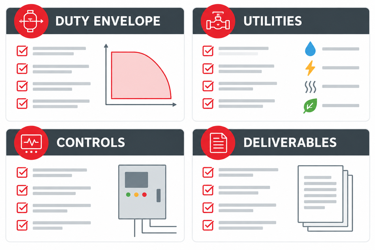
A useful request for quotation includes the completed gas envelope; process flow and battery limits; required cases; applicable standards and editions; driver and utilities; ambient and hazardous-area data; materials and corrosion basis; separation and drain philosophy; control narrative; relief, vent, and blowdown interfaces; noise and vibration requirements; testing; documentation; commissioning scope; and acceptance criteria. Cite the governing edition explicitly; the API standards catalog is the authority for checking current API document titles and editions before issue.
Ask the supplier to explain how its booster compressor system receives gas, controls inlet gas, and maintains the required outlet pressure. An explanation should distinguish an oil and gas package from compressed-air solutions and should justify the compressor solution for the gas source. Don’t accept booster compressor solutions that don’t define the case.
Ask each supplier to give the same case table. Normalize exclusions, auxiliary loads, cooler duties, pressure losses, spare parts, field services, and guarantee boundaries before comparing price. A lower package price can hide additional site equipment, utility demand, emissions handling, or operating restrictions.
Frequently Asked Questions
What is a booster compressor in oil and gas?
It’s a secondary compressor that raises already-pressurized gas to a higher required pressure.
Is there a maximum compression ratio for a booster?
There’s no single, universal value. Pressure ratio is an application review input. First, other factors such as gas properties, discharge temperature, volumetric efficiency, rod loads, driver margin, control state and operating flexibility may govern.
Does oil-free mean the delivered gas is contamination-free?
Non-lubricated cylinders remove one oil-injection path, but upstream contamination, packing leakage, wear debris, corrosion products, materials, and downstream equipment can still affect the gas. Define a measurable cleanliness target, sampling point, test method and acceptance criterion for the complete gas path.
Why is a suction scrubber important?
Compressors are designed to handle gas; ingress of liquids can damage the components. A scrubber and its drains and level protection help prevent damaging liquid ingress, but their performance must be checked across the expected inlet conditions.
What should be verified during commissioning?
Verify actual gas and duty case, stage pressures and temperatures, flow, defined power boundary, control and protection functions, cooling and drains, vibration, lubrication, leakage observations and the baseline for future monitoring.
Turn the Duty Envelope Into a Reviewable Package
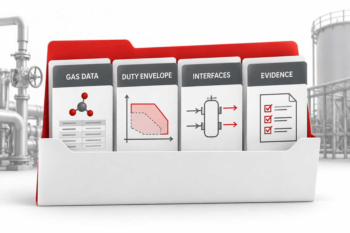
PanGeng can evaluate the gas composition, the suction case, the discharge requirement, flow basis, site conditions and the package interfaces. Start with the engineering worksheet above, then compare the available booster compressor configurations.
References & Sources
// SYS-DOC: WHY I WRITE THIS
[01] About PanGeng
PanGeng is an industrial gas compressor manufacturer based in Bengbu, Anhui, China. Since 2009, we have focused on the design, R&D, production, and manufacturing of customized gas compressor systems for oilfield, chemical, energy, hydrogen, nitrogen, biogas, and industrial air applications.
[02] Our Expertise
We write compressor guides based on real manufacturing and engineering experience, including hydrogen compressors, nitrogen compressors, booster compressors, medium and high-pressure air compressors, oilfield nitrogen injection systems, biogas compressors, and OEM/ODM custom compressor solutions.
Our engineering team supports customers from application analysis and compressor selection to production, factory testing, commissioning, spare parts, and after-sales service.
[03] Why You Can Trust This Content
The technical information in our articles is based on PanGeng’s in-house compressor design and manufacturing experience, current product capabilities, and project support for industrial clients in global markets. Our goal is to help buyers understand compressor types, pressure ranges, gas requirements, customization options, and long-term operating costs before making a purchasing decision.
CONTACT PROFILE
AUTHORITATIVE SOURCE
NAME
PanGeng Engineering Team
BRAND
PanGeng
COUNTRY
China
MODEL
B2B / OEM & ODM
EMAIL
pg20090705@163.com
PHONE
0552-4958225
WEBSITE
pgcompress.com