Get in Touch with Pangeng

Industrial Air Compressors for Oil and Gas: A Practical Selection Guide

Contents
show
Application Engineering Guide
When considering industrial air compressors for oil and gas, think air user first, then reach for the compressor catalog. Instrument valves, workshop tools, drilling support, N2 gen, and starting systems, to name a few, vary in their demands for pressure, purity, continuity, continuous operation, and site interface.
Define the service boundary, map every air demand, build the operating envelope, specify delivered-air quality, record site constraints, compare industrial compressor and driver architectures, and agree on acceptance evidence.
First Separate Compressed Air From Process-Gas Compression
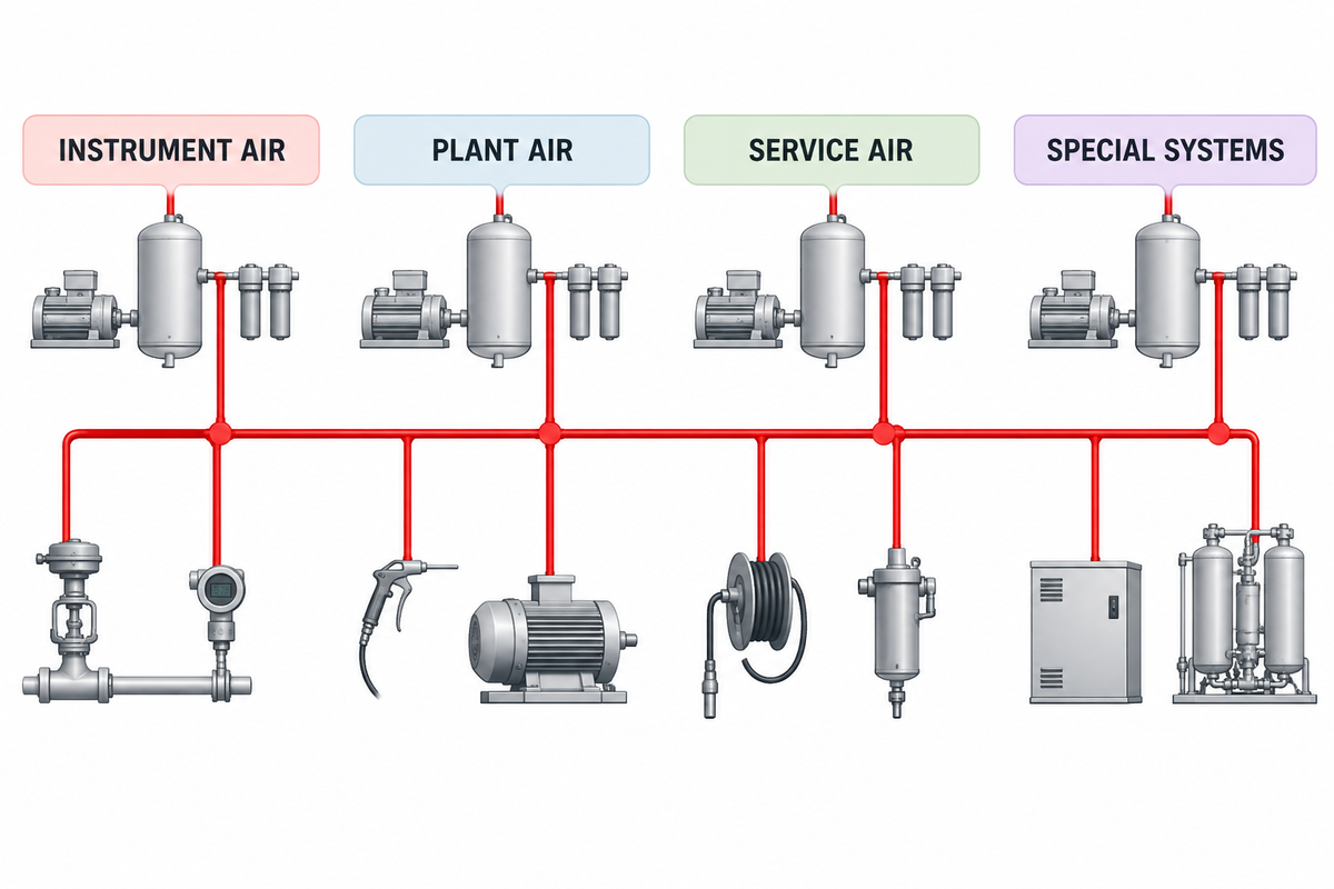
Compressed air is a plant utility. It can be used for continuous use to power pneumatic tools, instruments and starters. A process-gas compressor can handle natural gas, hydrogen, nitrogen, flare gas, and other process gases, and process air should likewise be qualified by the end user with a clearly defined service boundary.
In this case, the term “oil and gas compressor” can be interpreted in many ways. A request for plant air shouldn’t absorb a request for hydrocarbon gas. Equipment designed for atmospheric air should never be used for a process stream merely because the flow and pressure requirements may be similar.
Service Boundary Test
- If the duty is to provide compressed air, retain it in this manual.
- If the duty is to provide a process stream, route it to the process compression design basis.
- If a single package serves both purposes, describe the physical separation, contamination control and ownership of all interfaces.
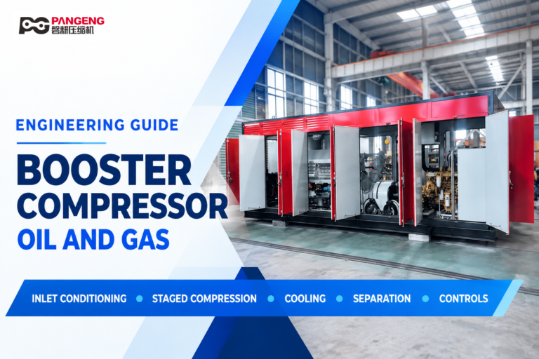
For process-gas boosting, staging, separation, and recycle control, see the process-gas booster compressor guide and overview of engineered gas compressor packages. The EPA instrument-air resource also shows the importance of distinguishing instrument-air supply from gas-driven pneumatic service. This guide covers air utilities.
Which Air Users Belong in the Compressor Air Duty Map?
List every user of the service and assign an owner; the EPA instrument-air resource illustrates why service boundaries should be explicit. Instrument air may be used to operate control valves, as well as safety-related pneumatic devices. Plant or utility air may be used to operate tools, as well as maintenance and service connections. Well-service air may be mobile and intermittent and may be exposed to outdoor conditions. Nitrogen-generating systems, starting air systems, and breathing-air systems may be subject to special treatment or safety requirements.
Don’t merge services just because they’re supplied from the same pressure header. A sudden demand swing on a tool connection shouldn’t be expected of an instrument-air header. Breathing air is a health and safety concern, and an ordinary compressor label wouldn’t satisfy the requirement for breathability.
Air Duty Map
| Service | Users | Demand pattern | Quality need | Interruption consequence |
|---|---|---|---|---|
| Instrument air | Actuators, controls | Steady with events | Project-defined clean, dry air | Loss of control or trip |
| Plant air | Tools, maintenance | Variable and intermittent | Fit for equipment | Reduced productivity |
| Service or drilling air | Mobile and field users | Campaign or shift based | Application specific | Activity delay |
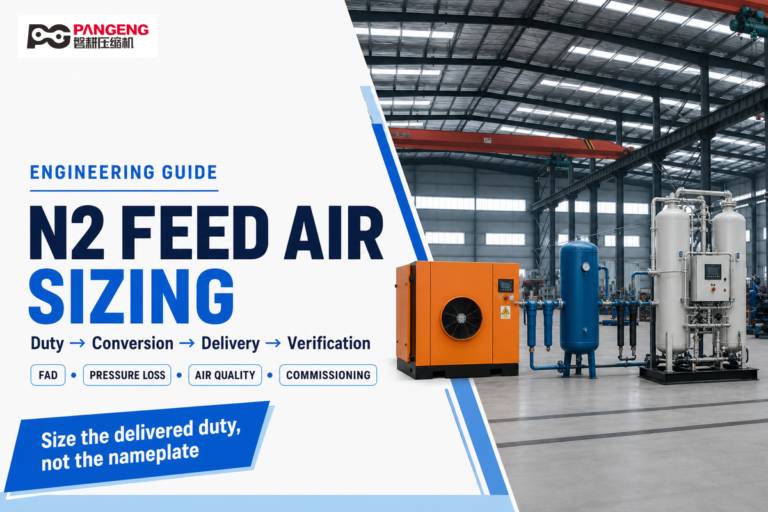
| Nitrogen-generator feed | Membrane or PSA package | Package dependent | Feed specification | Nitrogen shortfall |
| Starting air | Engines or turbines | Short, high-flow events | Equipment specific | Failure to start |
For each user, determine the required pressure, simultaneous demand, operating schedule, allowable interruption, and expected recovery time. This map will help determine how much storage the system needs and how redundant it should be. Without this information, statements like “100% standby” or “always on” are meaningless.
Convert Demand Into a Design Envelope
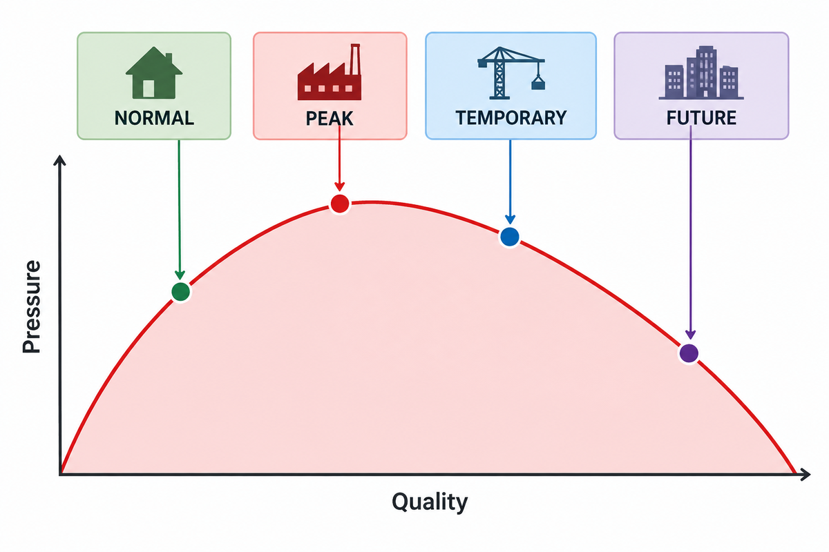
A single total flow isn’t a design basis. Consider recording minimum, normal, peak, temporary, and credible future demand. State if the flows are actual or referred to standard conditions including temperature, pressure, and humidity. Specify the pressure required at the farthest or the most sensitive user, rather than the pressure at compressor discharge.
Also include treatment and distribution pressure losses, receiver behavior, elevation, ambient conditions, and fouling allowance, in the design basis. An unexplained conservation margin in an energy-efficient design may result in a compressor operating in an inefficient unloading or cycling condition.
Demand Envelope Card
| Input | What to freeze | Why it matters |
|---|---|---|
| Flow | Minimum, normal, peak, duration, reference conditions | Defines capacity and turndown |
| Pressure | Point-of-use minimum and network loss | Prevents artificial discharge-pressure inflation |
| Environment | Ambient range, elevation, dust, salt, intake location | Affects cooling, capacity, and materials |
| Treatment | Filter and dryer pressure losses across life | Connects purity to usable pressure |
| Continuity | Critical load, allowable outage, restart time | Defines standby and storage |
| Growth | Named future users and timing | Avoids arbitrary oversizing |
For continuous demand, rather than arbitrarily selecting a compressor based on total nameplate demand, refer to the US Department of Energy compressed-air sourcebook, which views the storage and control of compressed air as an integrated system. Where an existing facility allows it, monitor actual air demand, and for a new facility, assess the assumptions underlying the air-demand estimate.
Which Compressor Architecture Fits the Duty?
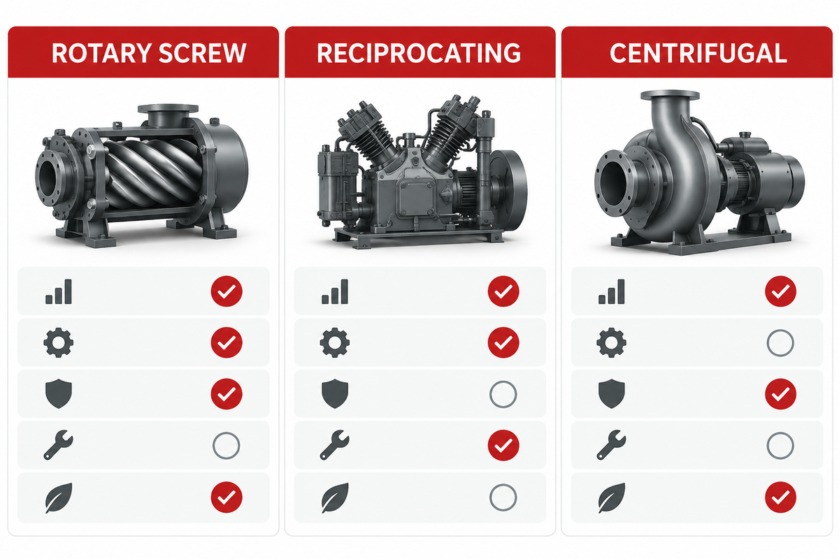
In general, rotary screw compressors are more suited for continuous service and Centrifugal compressors are for larger and steady-state demands. For intermittent demands, smaller flows and higher discharge pressures, consider a reciprocating compressor, but pay attention to pulsation, vibration and the number of stages. For larger flows and demands, centrifugal compressors may be better, providing the expected range is in line with the controls.
Architecture Fit Matrix
| Selection category | Rotary screw | Reciprocating | Centrifugal |
|---|---|---|---|
| Demand shape | Steady or variable industrial duty | Intermittent or discrete duty | Large, relatively steady duty |
| Pressure path | Common plant-air range; staged options exist | Strong fit for higher-pressure stages | Application and stage design dependent |
| Part-load review | Load-unload, modulation, or VSD behavior | Cycling, unloaders, and storage | Turndown and control boundary |
| Maintenance focus | Air end, separator, lubricant or element condition | Valves, rings, packing, pulsation and vibration | Aerodynamics, bearings, seals, and auxiliaries |
| Flow scale | Broad packaged range | Small to moderate flow by frame | Higher-flow applications |
| Footprint pattern | Compact package | Access around cylinders | Inlet arrangement dependent |
| Cooling review | Air end and aftercooler | Interstage and cylinder cooling | Intercooling and auxiliaries |
| Vibration focus | Isolation and alignment | Foundation and pulsation | Rotor dynamics and alignment |
| Package strategy | Single or sequenced units | Staged piston compressors | Base-load train |
Compare compressor proposals, including multi-stage arrangements, at the same inlet conditions, required discharge condition, flow reference, treatment scope, driver basis, and duty profile, using the US Department of Energy sourcebook as a system-level reference. For product families and configuration discussions, please see PanGeng’s industrial air compressor families.
What Air Quality Is Required at the Point of Use?
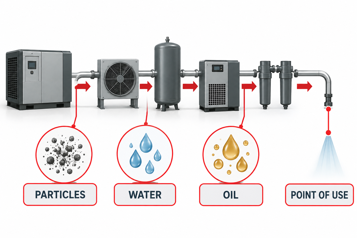
ISO 8573-1 provides a framework for classifying compressed-air purity by particles, water, and oil. The three attributes should be defined and named to a measurement location. “Clean air” is not a testable requirement, and a purity statement at the compressor outlet may not describe conditions after a long distribution header.
Oil-free compression removes oil from the compression chamber. It does not address other possible oil contamination in downstream air, nor does it remove possible contaminants from intake air. Delivered air quality depends on the condition of the piping, maintenance and sampling practices, and ambient conditions. Class 0 is a project or supplier specification within the framework of ISO, not a shorthand statement for assuming “no oil” can be measured.
Air Quality Boundary
- Name the user or header where quality applies.
- State particle, water, and oil requirements separately.
- Define operating pressure, temperature, and sampling conditions.
- Identify dryer type, filtration stages, drains, and condensate handling.
- Agree on the test method, instrument range, and acceptance criteria.
Pressure dew point should be based on the coldest exposure of the piping and equipment, including shutdown, as opposed to a default value on a climate label. Distinguish ordinary utility air from breathing air and other regulated uses. These services would warrant dedicated specifications and review.
Design for Onshore, Offshore, and Classified Locations
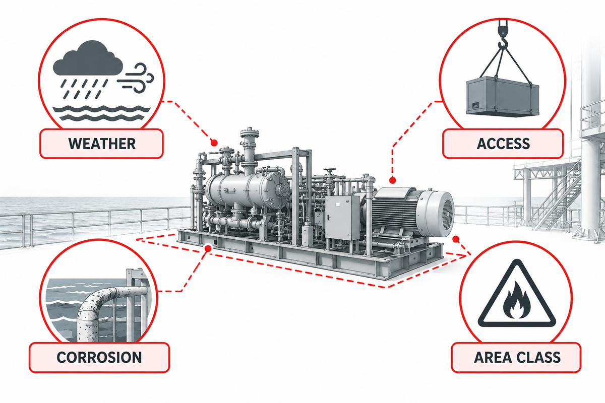
The safest and easiest arrangement may be to place the compressor in a suitable safe area room, while piping air to classified users. This isn’t always the case. The project team must define the classification of hazardous areas, the governing jurisdiction, equipment protection methods, ambient envelope, ventilation, gas detection interfaces, shutdown philosophy and the demarcation between the vendor and site scope.
There are a number of other offshore oil and gas factors including salinity, humidity, restricted space, lifting constraints, noise, and water drainage, as well as maintenance access. Location of the intake can affect performance. Hot recirculated cooling air, engine exhaust, vapors, sea spray and dust can reduce capacity and affect performance.
Site Interface Register
| Interface | Required project input | Named owner |
|---|---|---|
| Location | Area classification and safe-area boundary | Electrical/process safety |
| Environment | Temperature, elevation, salt, dust, rain, freeze | Site engineering |
| Utilities | Power, fuel, cooling, drains, instrument signals | Project utilities |
| Installation | Footprint, loads, access, lifting, transport envelope | Civil/layout |
| Operations | Noise, service clearances, consumables, spares | Operations/maintenance |
In the US, OSHA rules for hazardous locations govern the equipment and wiring in classified areas. Other jurisdictions apply different legal and standards frameworks. The RFQ should state the applicable framework as opposed to requiring the supplier to infer it from the term “oil and gas.”
Which Driver and Control Strategy Fit the Duty?
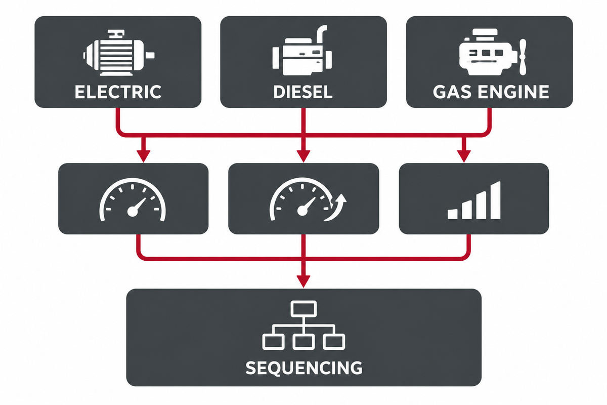
Electric drive is often preferred, especially in the case of power that’s reliable and suitable for starting. A Diesel drive can be used for mobile, temporary and remote equipment, and construction equipment, but introduces fuel logistics, emissions and weather protection, and engine maintenance. A gas engine driven package can be used for a remote equipment site if there’s an adequate fuel-gas supply; gas specification and starting, as well as the ventilation and exhaust of the package, then become design inputs.
For remote engines, see PanGeng’s air compressor packages.
Control selection follows demand, while installation details must also reflect applicable OSHA hazardous-location requirements. For load-unload control, a fixed-speed drive may work for control of known load and storage steps. Variable speed drive control may reduce unloaded operation, but depends on cooling, motor efficiency, harmonics, sequencing, and time at full load.
When several compressors share a common header, a master sequence should be used to assign base and trim roles, and to set standby units. The absence of a master sequence allows several compressors to operate simultaneously, leaving a standby unit to handle the demand.
What Determines Reliability Beyond the Compressor Block?
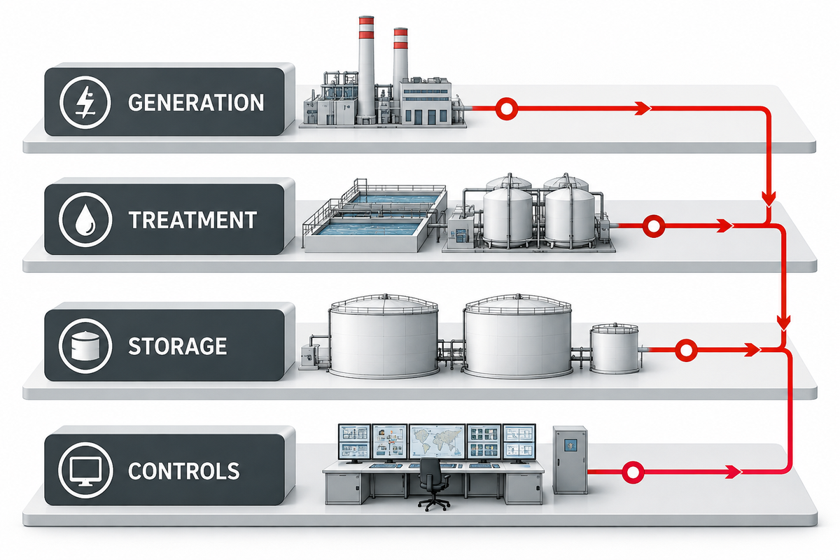
Each compressor in a duplex system should carry the main load after derating for ambient conditions and loss from treatment. Similarly, unplanned downtime should be addressed by accounting for potential failures in the shared dryer, filter, receiver, control panel, electrical feeder, cooling system, and discharge header.
Reliability Stack
- Generation: duty, trim, standby, and restart philosophy.
- Treatment: parallel or maintainable dryers, filters, drains, and isolation.
- Storage: Receiver volume is related to load steps, ride-through time, and control response time.
- Distribution: Pressure drop, branches and ring mains, low points, and drains.
- Controls: alarms, automatic changeover, permissives, remote signals, and failure states.
- Maintenance: Consumables and critical spares, as well as access for lifts and safe isolation.
For covered US installations, OSHA 29 CFR 1910.169 addresses air-receiver access, drainage, visible pressure indication, and spring-loaded safety valves. Treat that as one jurisdictional input, not a universal design code. The project must also identify the applicable pressure-vessel rules, inspection obligations, relief basis, and local authority requirements.
Storage capacity isn’t free. Receiver storage can buffer or smooth out short events. It can also moderate pressure changes, but if demand outpaces the available compressor output, the resulting shortfall will reduce header pressure. Before calculating storage, define the event, the minimum acceptable pressure, the available pressure band, and the required response.
What Acceptance Evidence Matters Beyond Catalogue Labels?
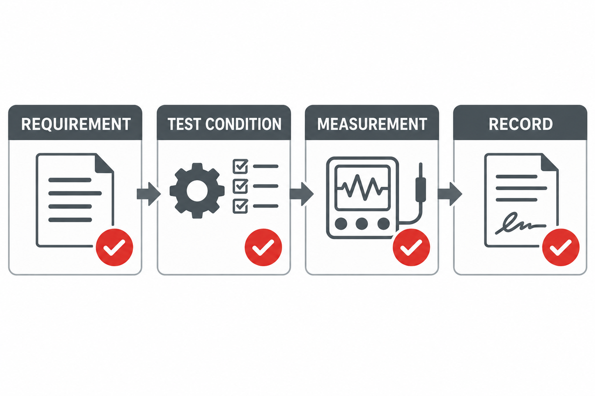
Turn each important claim into an observable acceptance criterion that can be checked against stated test conditions. Rated flow requires, at minimum, specification of inlet and reference conditions, while air-purity acceptance can reference ISO 8573-1. Delivered pressure requires specification of a measurement location. Dew point requires specification of the sampling point, operating state, and instrument and method to be used.
Acceptance Evidence Matrix
| Requirement | Freeze before test | Evidence |
|---|---|---|
| Flow and pressure | Conditions, measurement points, tolerance | Calibrated readings and corrected result |
| Air quality | ISO class components, sample point, stable state | Particle, water, and oil test records |
| Controls | Alarm, trip, changeover, restart, remote signals | Cause-and-effect test sheet |
| Receiver and relief | Design documents, set points, jurisdiction | Certificates and functional records |
| Mechanical condition | Run duration, loads, limits | Temperature, vibration, noise, leak inspection |
| Consumption | Operating case and boundary | Power or fuel measurement |
Factory and site acceptance tests verify equipment functions at the supplier’s works and under installed site conditions, respectively. A factory acceptance test verifies packaged functions at the supplier’s works, while a site acceptance test verifies the installed equipment functions under site conditions. Record power or fuel consumption at the defined operating case. If the site can’t reproduce the rated case, agree at the outset how corrections, deferred tests, and punch-list items will be addressed.
Send a Complete RFQ
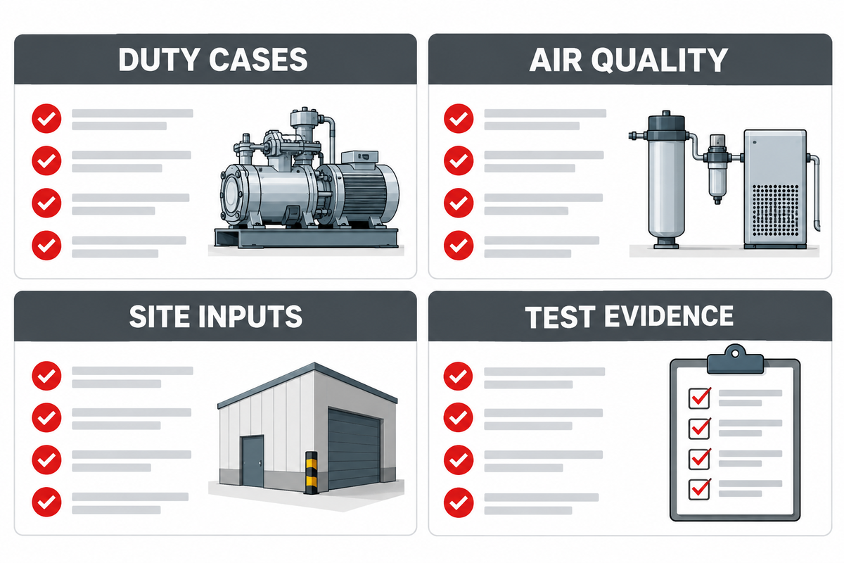
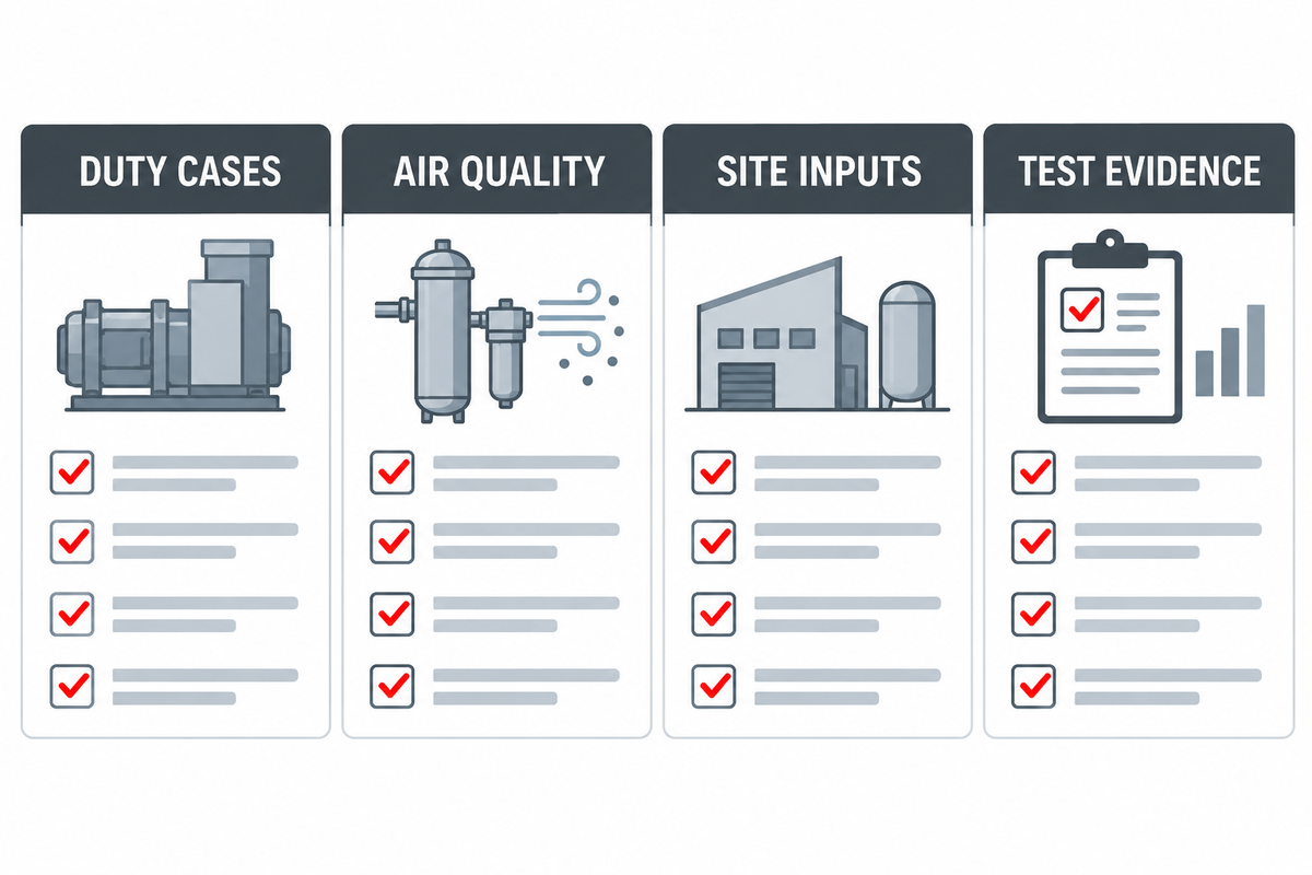
A useful RFQ gives suppliers a common design basis, including jurisdictional inputs such as OSHA air-receiver requirements where applicable. Include:
- service list and Air Duty Map;
- Normal, peak, temporary and future flow cases, with reference conditions;
- point-of-use pressure and distribution-loss allowance;
- particle, water, and oil requirements at named measurement points;
- ambient, elevation, intake-air, corrosion, enclosure, noise, and area-classification inputs;
- power or fuel data, starting restrictions, controls, communications and shutdown interfaces.
- Duty/standby philosophy, receiver events, dryer and filter arrangement, bypass and isolation needs.
- Applicable codes and standards, document language, inspection, FAT, SAT, certificates, spares and training.
- Required deviations list, to make exceptions visible rather than buried in quotes.
A common bidder data schedule with all assumptions listed allows the PanGeng Engineering team to review proposals, and choose a package based on stated site conditions.
Frequently Asked Questions
What are industrial air compressors used for in oil and gas?
They supply instrument air, plant and maintenance air, drilling or service air and starting and feed air for different packages, including nitrogen generators. How each facility uses the air varies. Keep atmospheric compressed air utilities separate from hydrocarbon process gas compression, because fluid definition, containment, safety basis and equipment selection differ.
What is the difference between instrument air and plant air?
Instrument air serves controls and pneumatic devices where the reliability and cleanliness may affect plant operation and/or safety. Plant air supports tools and utility users with a more variable demand. A facility may have generation equipment shared among many users, but it should protect the critical instrument air requirement through treatment, storage, priority, isolation or a separate header, as the case may be.
Which compressor type is best for an oil and gas facility?
Continuous utility air services may be met by many different designs using either reciprocating, rotary or centrifugal machines. Reciprocating machines may be used for intermittent services and/or higher pressure. Selection should be based on the range of demand, air quality architecture, ambient conditions, control behavior, maintenance, required redundancy, and vendor data evaluated at the same conditions.
Does oil-free mean the delivered air meets the required purity class?
No. Oil-free describes the compression architecture and reduces one contamination route, but delivered-air quality also depends on intake conditions, downstream piping, treatment, condensate management, maintenance, and sampling. Specify particle, water, and oil classes independently under ISO 8573-1, name the measurement point, and verify the result during acceptance.
When is a portable diesel air compressor appropriate?
Temporarily connecting to an instrument header should only be done after an approved interface plan is in place. The temporary connection must be made in the presence of the user after considering pressure, flow, fuel logistics, emissions, weather protection, treatment, and noise. It must be established whether the user can accept the air supply. Portable air compressors with a diesel driver can be used for construction, maintenance, temporary drilling support, pipelining and other service activities where power is unavailable.
Which System Requirements Determine the Right Machine?
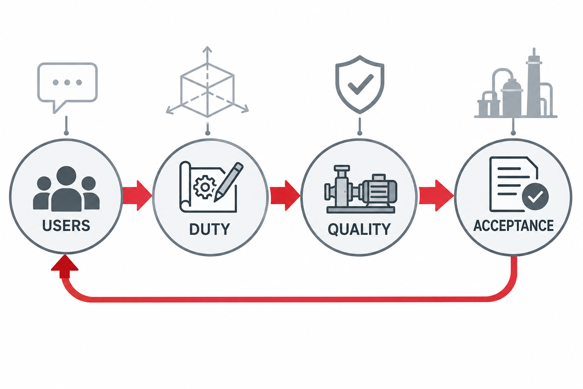
For compressed air, specify point-of-use quality and give users a basis for selection that enables them to compare architecture and driver fit, and to assess reliability and tests for critical requirements; the US Department of Energy sourcebook provides further system-level guidance.
References and Sources
// SYS-DOC: WHY I WRITE THIS
[01] About PanGeng
PanGeng is an industrial gas compressor manufacturer based in Bengbu, Anhui, China. Since 2009, we have focused on the design, R&D, production, and manufacturing of customized gas compressor systems for oilfield, chemical, energy, hydrogen, nitrogen, biogas, and industrial air applications.
[02] Our Expertise
We write compressor guides based on real manufacturing and engineering experience, including hydrogen compressors, nitrogen compressors, booster compressors, medium and high-pressure air compressors, oilfield nitrogen injection systems, biogas compressors, and OEM/ODM custom compressor solutions.
Our engineering team supports customers from application analysis and compressor selection to production, factory testing, commissioning, spare parts, and after-sales service.
[03] Why You Can Trust This Content
The technical information in our articles is based on PanGeng’s in-house compressor design and manufacturing experience, current product capabilities, and project support for industrial clients in global markets. Our goal is to help buyers understand compressor types, pressure ranges, gas requirements, customization options, and long-term operating costs before making a purchasing decision.
CONTACT PROFILE
AUTHORITATIVE SOURCE
NAME
PanGeng Engineering Team
BRAND
PanGeng
COUNTRY
China
MODEL
B2B / OEM & ODM
EMAIL
pg20090705@163.com
PHONE
0552-4958225
WEBSITE
pgcompress.com