Get in Touch with Pangeng

Booster Compressor for Pressure Testing: Engineering Selection Guide

Contents
show
A booster compressor for pressure testing isn’t chosen based on target pressure alone. The useful duty point is a moving envelope: inlet pressure can fall, required discharge pressure can rise during the fill, flow can vary along the curve, and the approved test procedure can control the medium, ramp, hold, acceptance criteria, and safeguards.
Content boundary: this guide explains how to define and verify a pressure-test duty. For product categories, available configurations, and supplier capability, use the booster compressor range page. Keeping those jobs separate prevents an application guide from competing with the product pillar.
1. Define
Freeze the test procedure, medium, volume, pressures, fill time, and cycle.
Freeze the test procedure, medium, volume, pressures, fill time, and cycle.
2. Match
Check the complete inlet-to-discharge envelope against a performance curve.
Check the complete inlet-to-discharge envelope against a performance curve.
3. Control
Plan ramp, stabilization, hold, inspection, and controlled venting.
Plan ramp, stabilization, hold, inspection, and controlled venting.
4. Prove
Specify records, vendor returnables, and acceptance evidence before purchase.
Specify records, vendor returnables, and acceptance evidence before purchase.
Map the Booster into the Pressure-Test System
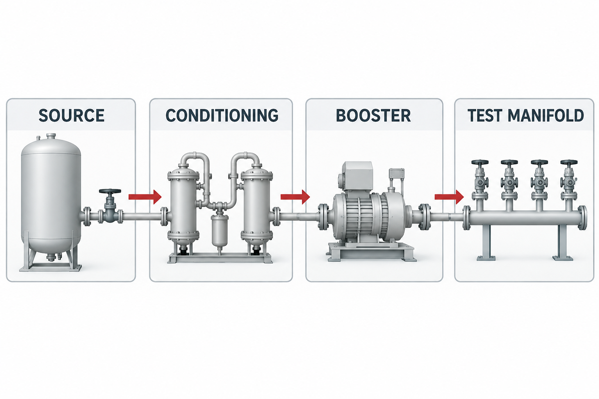
A booster in a gas cycle is normally placed downstream of the primary pressurized source and upstream of the high-pressure test manifold. The source could be plant compressed air, a nitrogen generator, a regulated cylinder bank, or another compressor. Conditioning equipment placed between the source and the booster could include a inlet receiver, filtration, or drying.
Don’t confuse a drive medium with process gas. In the case of an air driven booster, the large drive piston might be compressed air, and air, nitrogen, or another gas in the high-pressure section could be separately compressed. An electrically driven reciprocating booster has a different utility boundary; however, it too has defined process-gas inlet.
Pressure-Test System Boundary Map
Source → conditioning → inlet isolation/measurement → booster → cooling or receiver as required → discharge isolation and relief → calibrated test manifold → test article → controlled vent.
Record the minimum, normal, and maximum conditions at each battery limit. “Plant air available” is not a specification.
While the source is pressurized and flow is adequate, the booster is drawing gas. During operation a static gauge can read adequately, but can collapse due to an undersized line, regulator, filter or share plant demand. Manufacturer guidance also states that the performance of a gas booster is dependent upon the gas pressure and the performance curve for which it’s designed. [2]
Regardless of what the package is called, be it a air booster, pressure booster, air compressor booster, or booster air compressor, the same set of issues apply. The primary compressor must provide the required flow rate at the booster’s inlet while the compression stage produces the required outlet pressure. Nominal values such as 100 psi or 7 bar are examples only; they’re never a substitute for the actual duty envelope.
Choose the Test Medium Before Choosing the Booster
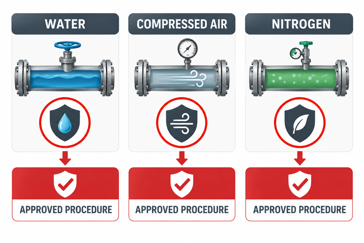
The approved test procedure should stipulate hydrostatic or pneumatic testing prior to specifying a compressor package. A supplier isn’t permitted to establish the governing test pressure, hold time, examination method, or acceptance criteria.
| Medium | Why it may be selected | Important boundary | Who decides |
|---|---|---|---|
| Water or another compatible liquid | Lower stored energy makes hydrostatic testing preferable when practicable. | Check contamination, corrosion, freezing, drainage, support load, and drying. | Owner/responsible engineer under the governing procedure. |
| Compressed air | Dry testing where liquid cannot be introduced or removed. | Pneumatic stored energy demands procedure-specific risk controls. | Approved test procedure—not equipment availability. |
| Nitrogen | Dry, inert medium where oxygen or moisture is unacceptable. | Nitrogen can displace oxygen; leaks and venting can create an asphyxiation hazard. | Approved procedure plus site EHS and ventilation assessment. |
The European Industrial Gases Association suggests using hydrostatic testing instead of pneumatic testing if possible and gives an example of the stored energy of compressed gases. [3] The U.S. Chemical Safety Board documents the invisible, rapid nature of the hazards of an oxygen-deficient nitrogen atmosphere. [4] Principles of these documents don’t supersede the local project code or the local jurisdiction.
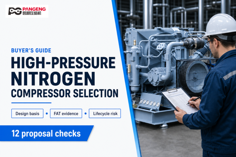
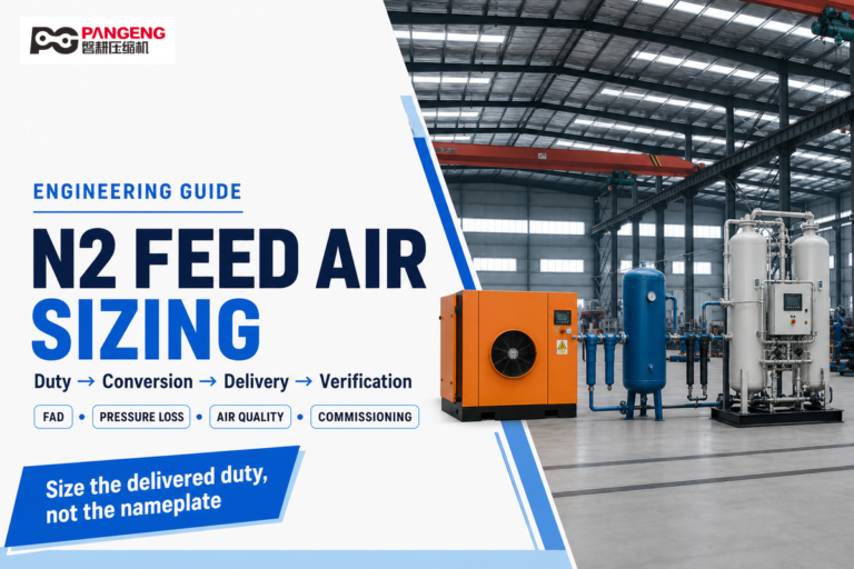
Keep adjacent design questions in their own lanes. Use the high-pressure nitrogen compressor selection guide when nitrogen-package configuration is the main decision, and the nitrogen feed-air sizing guide when the upstream air supply is the constraint. For a broader primer, compare the main booster compressor types and review how booster compression works. Those pages support the equipment decision; this guide remains focused on pressure-test duty, sequence, and acceptance evidence.
Convert the Test Requirement into a Duty Envelope
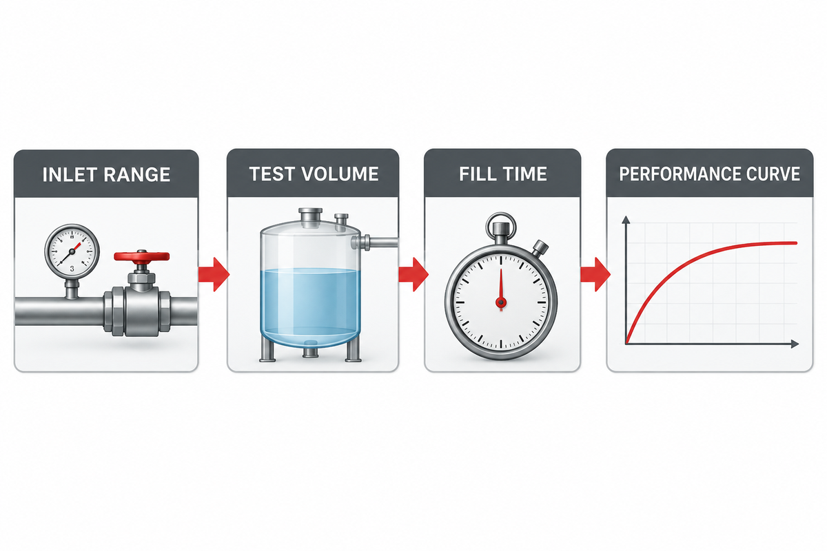
Start with a datasheet, not a part number. Define the gas composition and quality, total pressurized volume including hoses and manifolds, starting pressure, target pressure, inlet pressure range, temperatures, allowable fill time, cycles per hour, expected hold time, idle time, site altitude, and flow reference conditions.
Preliminary gas-quantity check
For an approximately isothermal ideal-gas estimate, the standard volume added is proportional to the test volume and the difference between final and initial absolute pressure:
This is an early planning estimate, not a final selection method. At high pressure, apply the appropriate compressibility treatment and use a supplier calculation or validated performance curve.
For an approximately isothermal ideal-gas estimate, the standard volume added is proportional to the test volume and the difference between final and initial absolute pressure:
ΔVstd ≈ Vtest × (P2,abs − P1,abs) / Pstd × Tstd / TtestThis is an early planning estimate, not a final selection method. At high pressure, apply the appropriate compressibility treatment and use a supplier calculation or validated performance curve.
Average required standard flow is derived by dividing estimated gas quantity by fill time. Although this value is useful, it won’t show whether the booster can provide the required flow at final pressure. This is evaluated by constructing booster curves to estimate the booster’s capacity and receiver fill time, considering the effects of performance of inlet and discharge pressure. [5]
What belongs in the Duty Envelope Worksheet?
- Gas composition, purity, moisture, oil, and particulate limits.
- Inlet minimum/normal/maximum pressure and temperature at the package boundary.
- The discharge pressure required at the defined delivery point, not at the compressor outlet.
- Total test volume, initial pressure, allowable fill time and expected leakage or consumption.
- Number of tests performed per hour or shift, run/hold/idle timing and recovery time between tests.
- Flow unit and reference temperature/pressure; “CFM” without units is ambiguous.
- The range of ambient temperature and pressure, classification for hazardous locations, available utilities, noise and cooling constraints.
Request the supplier to perform minimum, normal and maximum fill time profiles or curve calculations for inlet conditions. A “rated flow” doesn’t show the slowest part of the curve.
Select the Architecture from the Operating Envelope
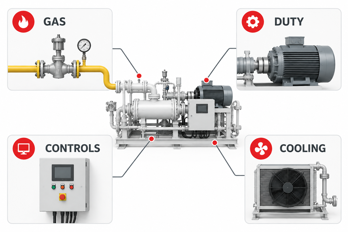
Air-driven boosters may be an attractive option for some applications, such as control of stalling at a static pressure, if a sufficient supply of drive air is available. Reciprocating, electrically-driven boosters may be more suitable for repeated or longer duty, especially if the cycle can be designed so that motor power, controls and cooling are fully integrated. Multiple stages are likely to be needed if the pressure or temperature rise can’t be tolerated for one stage.
| Decision category | Why it changes the package | Evidence to request |
|---|---|---|
| Pressure ratio across the envelope | Affects staging, volumetric efficiency, final-pressure flow, and heat. | Performance curves and predicted fill profile. |
| Gas composition and cleanliness | Controls wetted materials, seals, lubrication boundary, and contamination management. | Compatibility statement and material list. |
| Continuous vs. intermittent duty | Changes cooling, drive sizing, receiver strategy, and maintenance interval. | Declared duty rating and thermal assessment. |
| Control requirement | Determines pressure regulation, staged ramping, permissives, data logging, and integration. | Control narrative, alarm/trip list, and I/O schedule. |
| Site environment | May affect motor, instruments, ventilation, enclosure, and certification. | Compliance schedule tied to installation location. |
| Inlet conditioning | The presence of contaminants or moisture can change filtration, drying, and seal life. | Air quality required at the battery limit and conditioning scope. |
| Receiver strategy | A receiver can decouple booster systems from short peak demand but adds stored energy and controls. | Volume rationale, relief sizing responsibility, and operating sequence. |
| Cooling method | Air or water cooling affects utilities, discharge temperature, and installation layout. | Heat-rejection calculation and allowable ambient range. |
| Speed control | Variable speed or cycling logic can change turndown, heat, and response. | Control range, minimum stable operation, and alarm/trip setpoints. |
A universal “maximum ratio per stage” shouldn’t be applied. The design of the booster and the gas, inlet conditions and the materials used determine the operating envelope. Require the manufacturer to confirm the complete operating envelope.
Specification terminology. A booster compressor guide may use several names for related equipment. A high pressure booster, air pressure boosters, or a high pressure booster compressor can describe a machine that steps up the pressure of gas already compressed by a primary compressor. Some documents say pressure amplification, booster compressor unit, or high pressure air package. These labels do not prove that two booster systems have the same duty.
A typical plant pressure source asks if it supplies air at a baseline pressure continuously or only shows air at a baseline pressure while idle. The required outlet pressure and the pressure band required at the point of use must be paired with the inlet minimum. When the overall pressure ratio is high, a typical two-stage system may control temperature better, but only the manufacturer can confirm this for the gas being compressed.
The review of architecture also has to analyze the presence of contaminants, air quality required, materials compatibility, cooling and conditioning, and the chosen pressure regulator. Oil-injected boosters may be inappropriate where oil is added to a process gas that has to remain clean. These judgments are based on process gases, and the applicable level of cleanliness and not on a general list of common industrial applications.
Variable speed can alter turndown and energy consumption in motor-driven packages; it doesn’t alleviate the need to verify the curve. Pneumatic equipment supplied by an air compressor booster can have a smaller pressure lift than a pressure-test package. Similarly, high-pressure cylinder filling and pipeline stress testing are different operating cases even when boosters are used in both.
The laws of thermodynamics still governs compression heat and gas density, but preliminary equations can’t replace a tested curve. System flexibility comes from correctly defined battery limits, controls, and receivers; not from choosing among the main types of boosters by name. The practical question is how booster compressors work across the actual inlet, discharge, and cycle envelope. [7]
Build a Controlled Pressure-Test Sequence
Read terminology in context. A gas booster is sometimes called a booster pump, but it should not be confused with a liquid pressure pump or vacuum pump. The gas has already been compressed before the booster can act as a second compression stage. The booster then uses its drive mechanism to step up the pressure and provides high‑pressure output inside its rated envelope.
Typical applications include leak testing, proof testing, and other component qualification tests. The exact high pressure and test sequence depends on the project. Typical high-pressure ranges provided in marketing literature don’t indicate a safe duty point. Different types of compressors must be chosen in accordance with the specified gas and oxygen compatibility, inlet conditions, and the procedure.
inlet pressure above a safe limit may improve system performance but must remain within the approved inlet limits. The primary compression and booster ratio and final delivery pressure form one system and changing one boundary condition changes the other two. Therefore, for an inherently high-pressure process, an overall system review is needed, rather than reviewing a single discharge number.
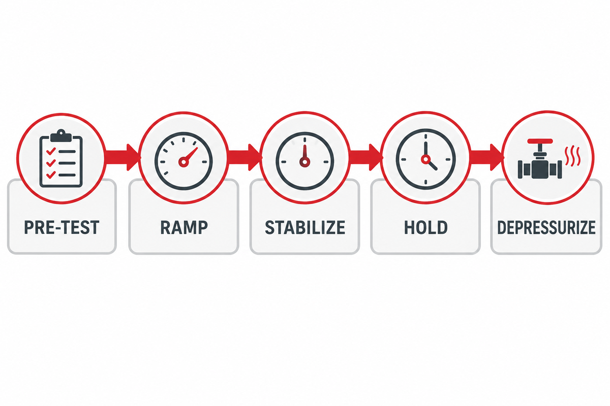
The booster supplies pressure; the approved procedure controls the test. Treat every phase as a different operating state and define limits, entry conditions, personnel responsibility, and records.
- Pre-test review: confirm test item identity, procedure revision, exclusion zone, instrumentation calibration, communications, and emergency stop.
- Purge or pre-fill: use the approved method, and confirm the medium and the vent destination before high-pressure operation.
- Controlled ramp: increase pressure as defined and pause for checks or stabilization.
- Stabilize: allow pressure and temperature to equilibrate before starting hold or decays.
- Hold and inspect: adhere to approved restrictions and methods for access and examination. Never, unless explicitly directed by a special engineered procedure, tighten fittings on a pressurized system.
- Review decay: interpret pressure changes along with temperature and test volume changes.
- Controlled Depressurization: vent to the approved location at a controlled rate taking into consideration noise, cooling, discharge forces, and nitrogen accumulation.
NASA pressure system requirements provide for explicit authorization and procedural controls for pneumatic testing. [1] A jurisdictional example from ABSA requires a staged pressurization and a safe distance control as well as a controlled depressurization; the provisions are specific to that jurisdiction and shouldn’t be adopted for a different project. [6]
Repeated tests create a maintenance duty that a nameplate can’t resolve. Frequently tightened test fittings can lose thread engagement, while pressure cycles and tightening loads add fatigue that may not be visible. The written procedure should therefore identify connector inspection, usage records, service-life limits, and rejection criteria. Rapid gas release can also cool connectors and cause local contraction, particularly where dissimilar materials meet.[8]
Don’t take successful proofs as authorization for unprotected close-range leak inspection. Plan remote gauges, cameras, or a secure enclosure, and permit entry only after review of those safeguards. The commercial boundary is relevant. A supplier delivering a booster as a single piece of equipment, a factory made pressure assembly, or equipment assembled on site, doesn’t automatically create the same design, documentation, and assessment requirements on the supplier. Identify that boundary in the RFQ and confirm it with the governing jurisdiction. [8] [9]
Build Acceptance Evidence into Every Test Phase
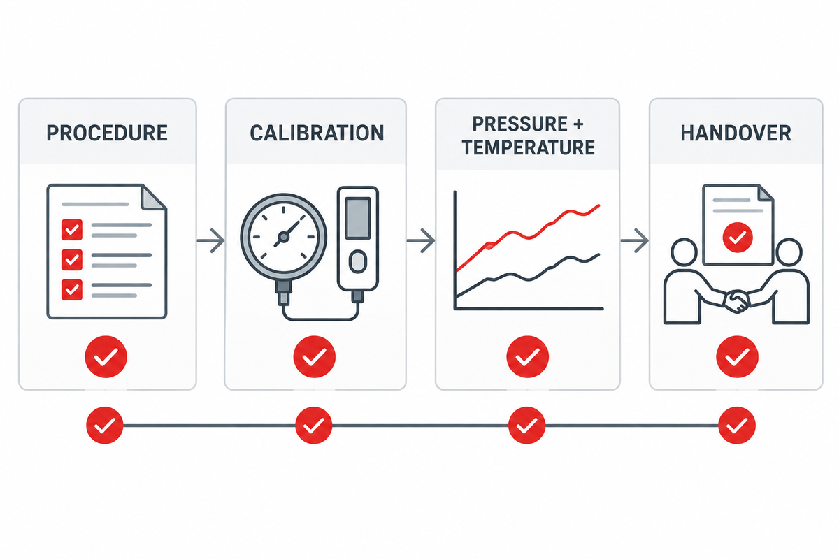
A test is auditable if another qualified person can evaluate the test and determine how and why the test passed. The final pressure reading is only a small piece of evidence.
| Phase | Minimum evidence | Common ambiguity prevented |
|---|---|---|
| Pre-test | Item ID, boundary drawing, procedure/revision, authorization, instrument IDs and calibration status. | Wrong item, wrong boundary, or expired instrument. |
| Ramp | Timestamped pressure and temperature, increments, pauses, observations, alarms, and deviations. | Uncontrolled overshoot or undocumented interruption. |
| Stabilization | Start criterion, elapsed time, temperature trend, and approval to begin hold. | Thermal settling mistaken for leakage. |
| Hold/inspection | Required duration, actual duration, allowable variation, inspection result, witness. | “Held pressure” without defined acceptance. |
| Vent/restoration | Controlled depressurization complete, zero-energy verification, test equipment removed, system restored. | Residual pressure or an incomplete handback. |
Prior to a test, come to an understanding on the data rate, accuracy of the sensors, the time source for the timestamp, how and in what format the data will be reported, and ownership of the data. If a package logger is used, define how raw data and audit trails will be extracted, not just whether a display is available to show a trend.
NASA’s pressure-system requirements provide an authority example for documenting authorization, instrumentation, and procedural control; the project procedure and jurisdiction remain controlling. [1]
Diagnose Slow Fill, Instability, and Excess Heat
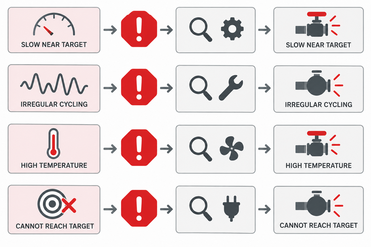
| Symptom | Check first | Possible boundary | Safe next step |
|---|---|---|---|
| Fast initially, very slow near target | Actual inlet and discharge pressures against the curve. | Normal curve behavior, excessive pressure ratio, undersized unit, or inlet decline. | Compare recorded points with the approved supplier prediction. |
| Irregular cycling | Drive supply, process-gas inlet stability, regulators, filters, valves, and leakage. | Starved inlet, control hunting, contamination, or worn sealing components. | Stop under the operating procedure and isolate before inspection. |
| High discharge temperature | Cycle frequency, cooling condition, pressure ratio, gas and ventilation. | Duty overload, cooling restriction, wrong operating point, or mechanical problem. | Do not bypass a temperature trip; obtain manufacturer review. |
| Cannot reach target pressure | Static end-pressure relationship, relief/regulator settings, leaks, inlet and drive conditions. | Duty mismatch, system leakage, valve issue, or protection setting. | Depressurize safely and test boundaries systematically. |
Don’t solve a slow test by reducing relief valve pressure, increasing drive pressure above the rating, blocking a vent, or ignoring a temperature alarm. The corrective action must be within the scope of the package datasheet or approved procedure.
The HSE pressure-testing guidance supports isolating and depressurizing before connector or hose inspection and maintaining test fittings across repeated cycles. [8]
Use a Quote-Ready Pressure-Test Booster Checklist
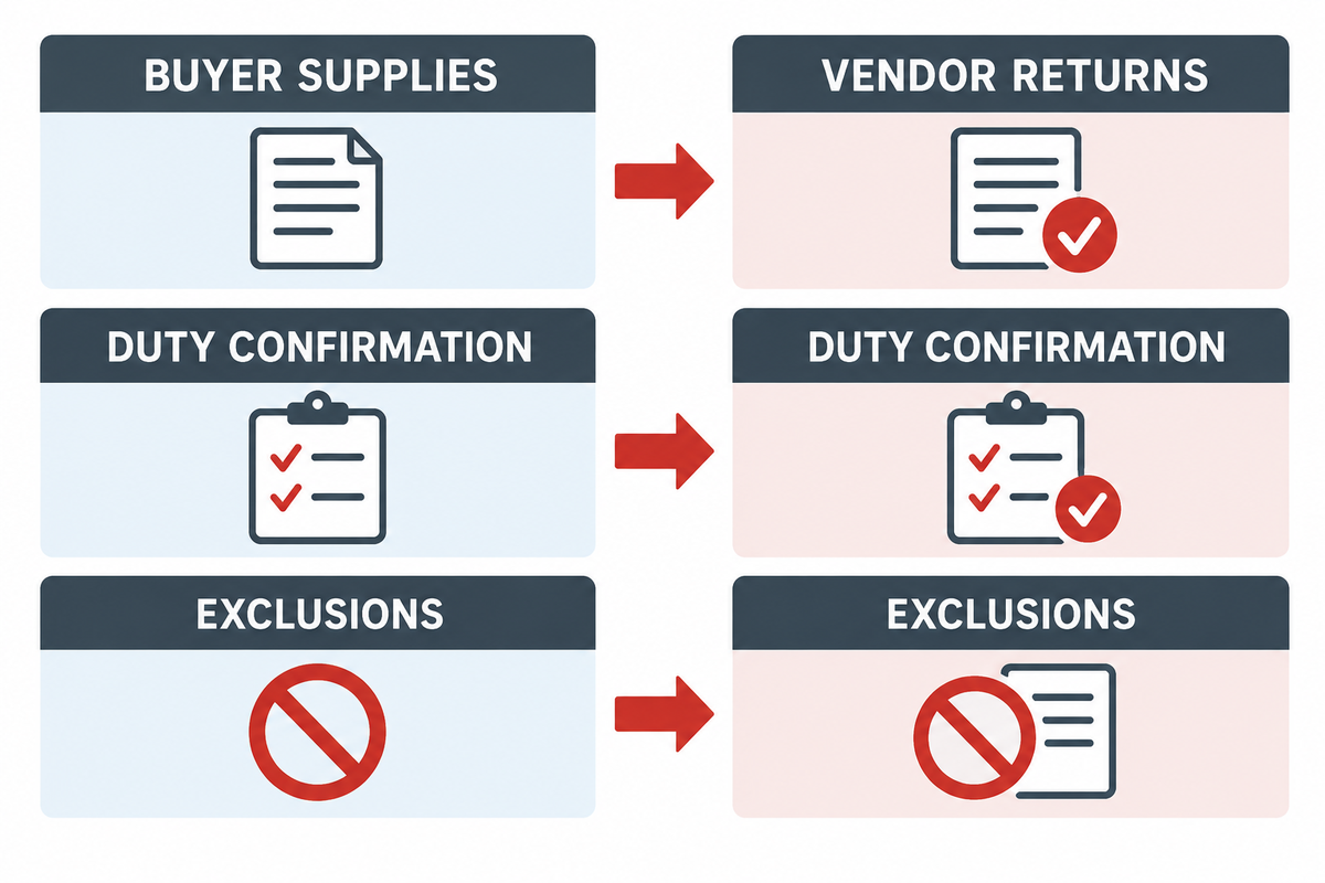
A good RFQ gives suppliers the ability to quote the same duty and disclose assumptions. It also separates buyer inputs from vendor required proofs.
Buyer supplies
- Gas and contamination limits
- Inlet/discharge envelope
- Volume, fill time, and cycle
- Site and utilities
- Battery limits and interfaces
- Codes and inspection requirements
Vendor returns
- Curve-based duty confirmation
- Utility and thermal assessment
- P&ID, GA, datasheets, materials
- Control narrative and alarm list
- Inspection/test plan and FAT method
- Manuals, certificates, spares, exclusions
State whether the supplier is responsible for inlet conditioning, receivers, cooling, and the high-pressure manifold. Relief devices, vent piping, instruments and controls integration, installation, commissioning and training. State any other exclusions. For example, some of Maximator’s literature identifies operating documentation, drawings, and literature among the package documents, to illustrate why deliverables should be named rather than assumed. [7]
Frequently Asked Questions
What does a booster compressor do in a pressure-testing system?
It accepts gas that’s already pressurized and raises it to the higher pressure required by the approved test procedure. It normally sits between the conditioned source and the high-pressure manifold or test article. Usable output depends on inlet pressure and flow, discharge pressure, gas properties, drive conditions, temperature limits, and cycle, so pressure alone isn’t a complete duty specification.
How do I size a booster compressor for a pressure test?
Define total connected volume, starting and target absolute pressures, gas composition, inlet range, allowable fill time, cycles per hour, hold time, temperature, site conditions, and flow reference basis. Estimate gas quantity for preliminary planning, then check the entire pressure-dependent filling path against the supplier’s performance curve, including compressibility, thermal stabilization, piping volume, leakage allowance, and recovery time.
Should I use compressed air or nitrogen for pneumatic pressure testing?
The approved procedure must select the medium using the governing code, component compatibility, contamination limits, and risk assessment. Air may be acceptable where oxidation and moisture are controlled. Nitrogen can provide a dry inert medium but creates an oxygen-deficiency hazard. Pneumatic testing stores more energy than hydrostatic testing and needs procedure-specific safeguards and authorization.
Why does booster flow fall as test pressure rises?
The booster works against increasing discharge pressure. Volumetric efficiency, pressure ratio, available drive power, valve losses, temperature, and inlet conditions change during the cycle. A nameplate flow at one condition can’t predict final-pressure delivery; use the actual performance curve or the supplier’s filling-time method.
What records should a pressure-test package produce?
Retain the approved procedure and authorization, test item identity, instrument and calibration records, pressure and temperature history, timestamps for ramp, stabilization and hold, inspection or leak results, acceptance criteria, deviations and approvals, controlled depressurization confirmation, and the final report. Project or code requirements may add witness points and certificates.
Define the Test Before Selecting the Booster
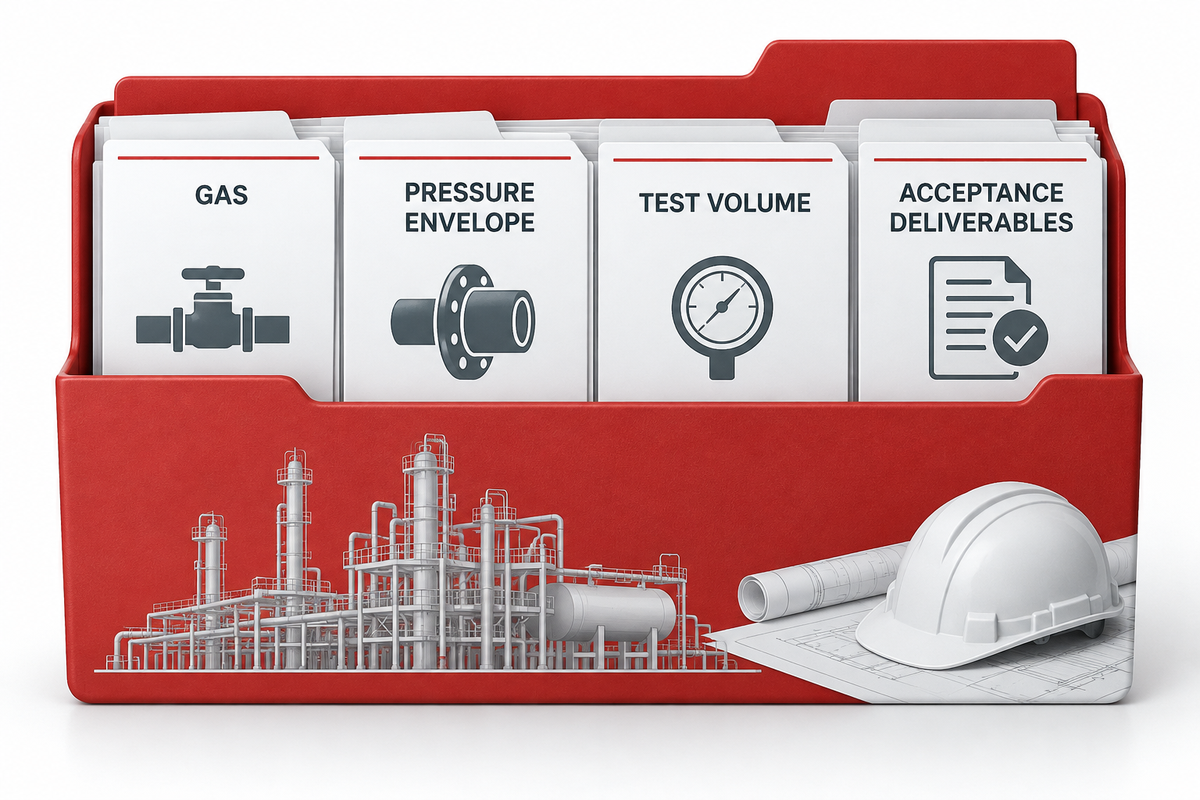
A quote becomes useful when it includes the gas, complete pressure envelope, test volume, fill time, cycle, site conditions, battery limits, and acceptance deliverables. PanGeng can review that duty package and identify the information still needed for a curve-based selection. The package-document examples in published booster literature show why deliverables should be named explicitly.
Discuss Your Pressure-Test DutyReferences and Sources
- NASA, Pressure Systems Safety.
- ProTech Pumps, Gas Booster Selection.
- EIGA Doc 254, Guideline for Pressure Testing of Field-Installed Piping and Equipment.
- U.S. Chemical Safety Board, Hazards of Nitrogen Asphyxiation.
- HII Pumps, Gas Boosters performance information.
- ABSA AB-522, Standard Pneumatic Test Procedure Requirements.
- Maximator, Air Driven High Pressure Gas Boosters.
- There are specific safety requirements for pressure testing. (UK HSE, Safety Requirements for Pressure Testing, GS4).
- UK HSE, Manufacture or Supply of Pressure Systems.
// SYS-DOC: WHY I WRITE THIS
[01] About PanGeng
PanGeng is an industrial gas compressor manufacturer based in Bengbu, Anhui, China. Since 2009, we have focused on the design, R&D, production, and manufacturing of customized gas compressor systems for oilfield, chemical, energy, hydrogen, nitrogen, biogas, and industrial air applications.
[02] Our Expertise
We write compressor guides based on real manufacturing and engineering experience, including hydrogen compressors, nitrogen compressors, booster compressors, medium and high-pressure air compressors, oilfield nitrogen injection systems, biogas compressors, and OEM/ODM custom compressor solutions.
Our engineering team supports customers from application analysis and compressor selection to production, factory testing, commissioning, spare parts, and after-sales service.
[03] Why You Can Trust This Content
The technical information in our articles is based on PanGeng’s in-house compressor design and manufacturing experience, current product capabilities, and project support for industrial clients in global markets. Our goal is to help buyers understand compressor types, pressure ranges, gas requirements, customization options, and long-term operating costs before making a purchasing decision.
CONTACT PROFILE
AUTHORITATIVE SOURCE
NAME
PanGeng Engineering Team
BRAND
PanGeng
COUNTRY
China
MODEL
B2B / OEM & ODM
EMAIL
pg20090705@163.com
PHONE
0552-4958225
WEBSITE
pgcompress.com