Get in Touch with Pangeng


Updated August 2026 · Technical review by Anhui PanGeng Gas Compressor Co., Ltd.
A hydraulic air compressor is a compressed-air package, also called a hydraulic driven air compressor, that uses pressurized hydraulic oil from a host machine to turn a hydraulic motor, which drives an air end. These driven air compressors can put on-demand air on a service truck, utility vehicle, drilling rig, or other mobile platform without adding a separate diesel engine. Successful integration, however, depends on matching two systems at once: the air demand at the tool and the hydraulic power, cooling, plumbing, and controls available on the host.
This guide covers that engineering work. It doesn’t rank models, publish product performance, quote prices, or replace a manufacturer-approved installation. Instead, it shows how to define demand, calculate a first-pass power budget, inspect the return and case-drain paths, plan heat rejection, commission the installation, and diagnose symptoms with measurements.
Direct answer: Choose a hydraulic air compressor only after the required air flow and pressure have been converted into a duty cycle, then verify that the host can supply the required hydraulic flow and differential pressure during the identical operating state without exceeding motor speed, return-pressure, case-pressure, temperature, hose, reservoir, or filtration limits.
Air sideFlow, pressure, air quality, duty cycle
Hydraulic sideFlow, differential pressure, speed, torque
Thermal sideOil temperature, cooler capacity, airflow
Control sideEnable logic, unload, shutdown, interlocks
Start with the Complete Hydraulic-to-Air System Boundary
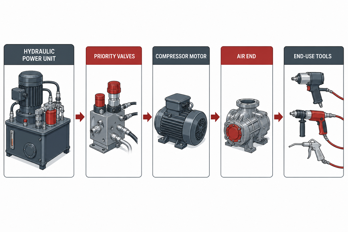
The compressor package is only one node in a larger energy path. The host engine or electric prime mover drives a hydraulic pump; valves and lines deliver flow to the compressor motor; the motor drives the air end; the separator, cooler, controls, receiver, and distribution system condition the air before it reaches the work. Restrictions or control errors anywhere along this path can appear as low compressor output.
This distinction matters because hydraulic pressure isn’t converted directly into equal air pressure. Hydraulic flow and pressure produce motor speed and torque. The air end then produces air flow and pressure within its own approved operating envelope. Raising a hydraulic relief setting doesn’t guarantee more air, and it can overspeed or overload the package if motor displacement and controls aren’t considered.
ISO 4413 frames hydraulic-fluid-power safety and system requirements across design, construction, modification, installation, use, and maintenance. That lifecycle view is useful even when a particular installation follows additional regional rules: the interface cannot be treated as a one-time purchase specification.
Boundary rule: Document the hydraulic power unit, priority valves, relief setting, supply and return lines, case drain, reservoir, filters, cooler, compressor motor, air end, separator, receiver, controls, hoses, and end-use tools as one operating system. Keep each component’s published limits visible.
Build an Air-Demand Envelope Before Looking at Hydraulic Power
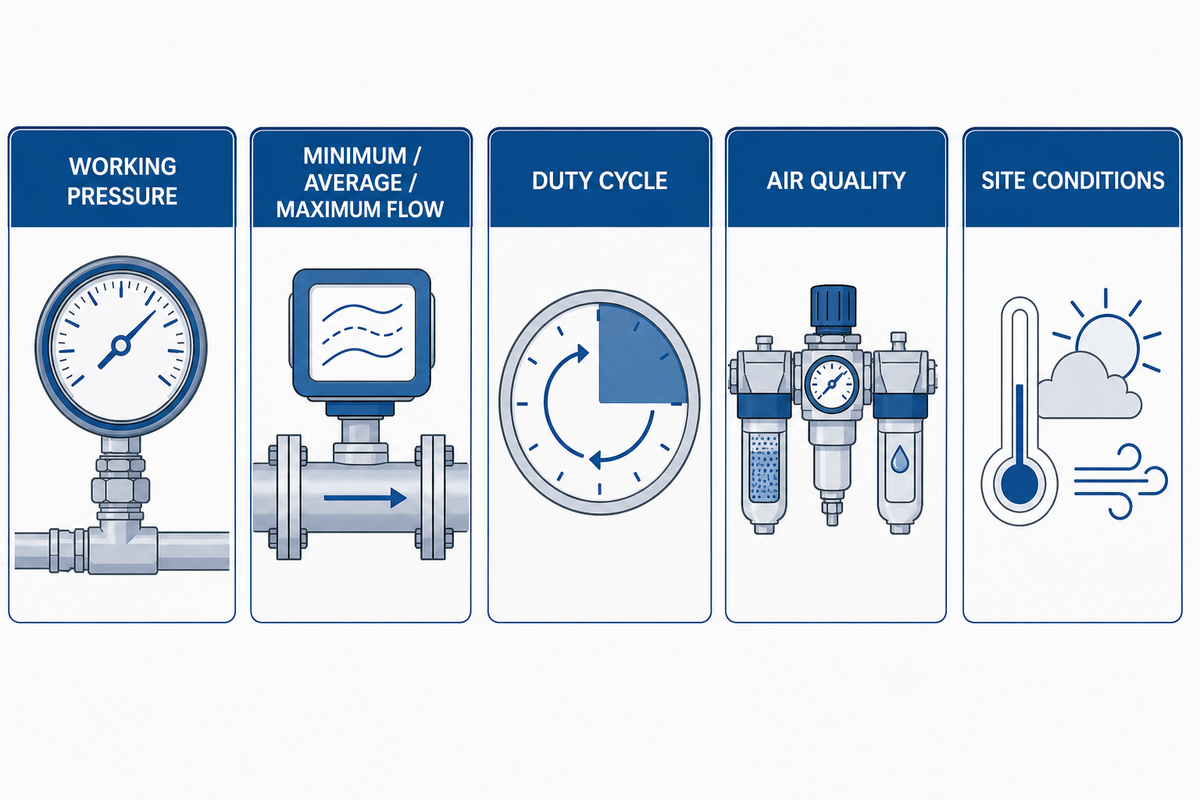
Begin at the point of use. List every pneumatic tool or process, the pressure required while it’s working, the flow it consumes in CFM or SCFM on a stated reference basis, how long it runs, and which loads can overlap. Nameplate consumption isn’t enough when a tool has a startup surge, a worn nozzle, a long hose, or an intermittent pattern.
The Compressed Air & Gas Institute sizing brief recommends distinguishing minimum, average, and maximum demand and separating continuous from intermittent uses. It also notes that storage can support a short peak but can’t replace compressor capacity for a sustained load. For mobile equipment, that means a receiver may smooth a wrench cycle, yet it can’t make an undersized package support continuous blasting or a long-duration air motor.
After the demand list is agreed, use the hydraulic compressor CFM sizing calculator to organize the air-side inputs. Treat its result as a planning value, then reconcile it with supplier data and measured pressure at the point of use.
| Input | What to record | Why it changes selection |
|---|---|---|
| Working pressure | Pressure at the tool while flowing, not only receiver cut-out pressure | Hose, coupler, dryer, and regulator losses consume pressure |
| Minimum / average / maximum flow | SCFM or another clearly defined reference basis | Separates base load from short peaks |
| Duty cycle | Run minutes, rest minutes, shifts, and simultaneous tools | Determines continuous power and heat rejection |
| Air quality | Particles, moisture, and oil limits at the point of use | Adds treatment, pressure loss, maintenance, and temperature constraints |
| Site conditions | Ambient temperature, altitude, humidity, dust, and ventilation | Changes inlet density, cooling margin, and filter loading |
| Simultaneous demand | Tools and processes permitted to operate together | Prevents separate nameplate loads from being summed incorrectly |
| Distribution path | Hose length, internal diameter, couplers, dryer, filter, and regulator | Reveals pressure loss between receiver and working tool |
| Receiver function | Peak duration, recovery time, cut-in, and cut-out basis | Separates short storage support from sustained compressor capacity |
| Verification point | Gauge, flow meter, and test location used for acceptance | Keeps quoted and measured conditions comparable |
Keep actual and reference air flow distinct. Values stated at standard conditions are not the physical volume entering the compressor at altitude or high inlet temperature. Record the reference definition used by the compressor supplier and the site conditions used by the project. ISO 1217 is the current published international reference for acceptance testing of displacement compressors, but ISO lists the 2009 edition as due for revision; purchase documents should therefore state the agreed edition and test basis rather than saying only “tested to ISO.”
Let the duty guide architecture, not the other way around
Hydraulic rotary screw and hydraulically driven reciprocating air compressors can respond differently to continuous load, intermittent peaks, unloading, pulsation, cooling, and maintenance. Don’t turn that distinction into a universal winner. Use the measured duty cycle, required air quality, space, mass, noise, lifecycle cost, ambient condition, and the supplier’s approved operating envelope to decide which architecture deserves detailed review; the hydraulic compressor comparison tool can structure that discussion without replacing the approved performance map.
Translate the Air Duty into a Hydraulic Power Budget
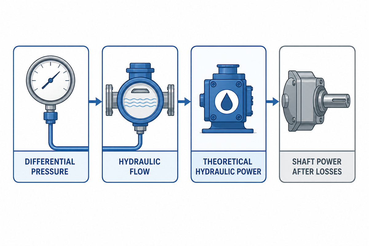
Once the air requirement is defined, obtain the approved compressor input requirement from the package supplier. Then compare it with the hydraulic power actually available at the installation point while other machine functions are active. Pump nameplate flow at high engine speed isn’t proof of simultaneous capacity at hot idle, during crane movement, or through a priority circuit.
The variables and efficiency terms in the Danfoss motor technical information provide a manufacturer-source cross-check for this first-pass power method; its product limits still belong only to the motor documented there.
For a first-pass imperial calculation, theoretical hydraulic horsepower is:
Hydraulic hp (theoretical) = pressure differential (psi) × flow (gpm) ÷ 1,714
Use differential pressure across the motor, not merely the supply-gauge reading. The motor return pressure reduces usable differential pressure. Mechanical power at the shaft is lower after volumetric and mechanical losses, while the hydraulic system must also carry line and control losses.
Worked example, not a PanGeng product rating: a hypothetical circuit delivering 20 gpm (75.7 L/min) at a 2,000 psi (138 bar) differential contains 23.3 hp (17.4 kW) of theoretical hydraulic power. If an explicitly assumed combined motor efficiency is 85%, estimated shaft power is about 19.8 hp (14.8 kW). This is a screening calculation only. Final selection must use the chosen motor’s manufacturer data across speed, pressure, temperature, viscosity, and case-pressure conditions.
Unit discipline: conversion references are not operating limits. For calculation handoffs, 1 US gpm equals 3.785 L/min, 1 psi equals 0.06895 bar, 1 hp equals 0.7457 kW, 1 in³/rev equals 16.387 cm³/rev, and a 1 °F temperature interval equals 0.556 °C. Keep unrounded values through the calculation and round only the reported result so unit conversion does not create false margin.
Do
- Measure flow and pressure at the compressor branch.
- Check hot-oil operation and simultaneous machine loads.
- Include valve, line, return, and cooler losses.
Do not
- Equate relief setting with continuous motor inlet pressure.
- Assume reservoir storage creates sustained hydraulic power.
- Increase pressure before checking flow and speed.
Verify Hydraulic Motor Speed, Torque, and Overspeed Protection
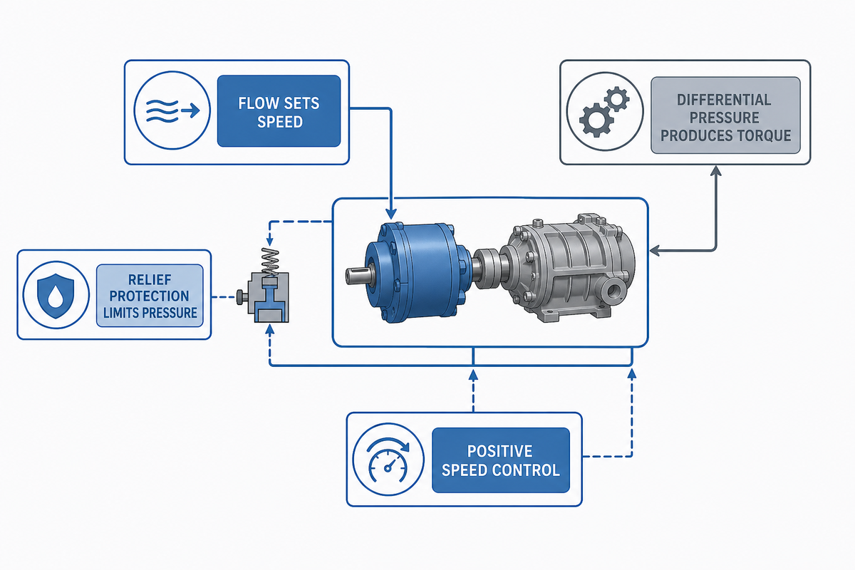
Hydraulic flow primarily sets motor speed; pressure differential produces torque. Motor displacement links the two. In simplified imperial form, ideal speed is approximately 231 × flow in gpm ÷ displacement in cubic inches per revolution. Actual speed differs because volumetric efficiency changes with operating conditions. Use the motor’s published performance map for the final value.
Danfoss’s current MP1 motor technical information illustrates the variables a motor manufacturer ties together: flow, displacement, speed, pressure differential, torque, power, efficiency, viscosity, temperature, and case pressure. Its numeric limits are product-specific and must not be copied to a different motor, but the measurement framework applies broadly.
Plan a positive speed-control method. Flow control or a properly designed load-sensing and priority arrangement must keep the compressor inside its approved speed band as engine rpm and other hydraulic functions change. Relief protection limits pressure; it isn’t an overspeed device. Controls should also prevent compressor engagement when oil is too cold, return paths are blocked, cooling is unavailable, or the host is in an unsafe state.
Measurement priority: record motor inlet and outlet pressure in psi or bar, hydraulic flow in gpm or L/min, motor or air-end speed in rpm, case-drain pressure in psi or bar, oil temperature in °C, and compressor air output in CFM on one timestamp. One pressure reading cannot reveal whether the problem is flow, restriction, load, speed, or control.
Design the Return Line, Case Drain, Reservoir, Filtration, and Hoses as One Circuit
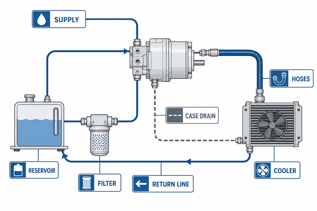
Adequate supply power can’t prevent motor failure if oil can’t leave freely. Return-line pressure adds load to the outlet side and reduces useful differential pressure. Undersized hoses, quick couplers, restrictive filters, a small cooler, a high reservoir entry, or a shared return carrying another function can produce backpressure that rises sharply with hot flow, or, for some restrictions, with cold viscous oil.
Where the motor design requires one, a dedicated case drain carries internal leakage back to the reservoir and controls housing pressure. It isn’t an optional overflow tube. Route it according to the motor and package instructions, avoid a check valve or restriction unless expressly approved, protect it from damage, and verify case pressure at the defined measurement point. Don’t join it to a high-pressure or unstable return simply because the fittings are convenient.
ISO 4406:2021 provides the current coding method for contamination by solid particles in hydraulic fluid. The code is a reporting method, not a universal cleanliness target. Set the target from the most sensitive component, the fluid, the operating environment, and supplier requirements; then define sampling location, flushing acceptance, filter rating, clog indication, and sample handling.
Hydraulic hose is also a system component, not a commodity chosen only by thread size. The scope of SAE J1273 covers selection, routing, fabrication, installation, replacement, maintenance, and storage of hose assemblies. Project review should include working and surge pressure, temperature, fluid compatibility, bend radius, abrasion, impulse, twist, restraint, inspection access, and consequences of a pinhole leak.
Treat Heat Rejection as a Continuous-Duty Calculation
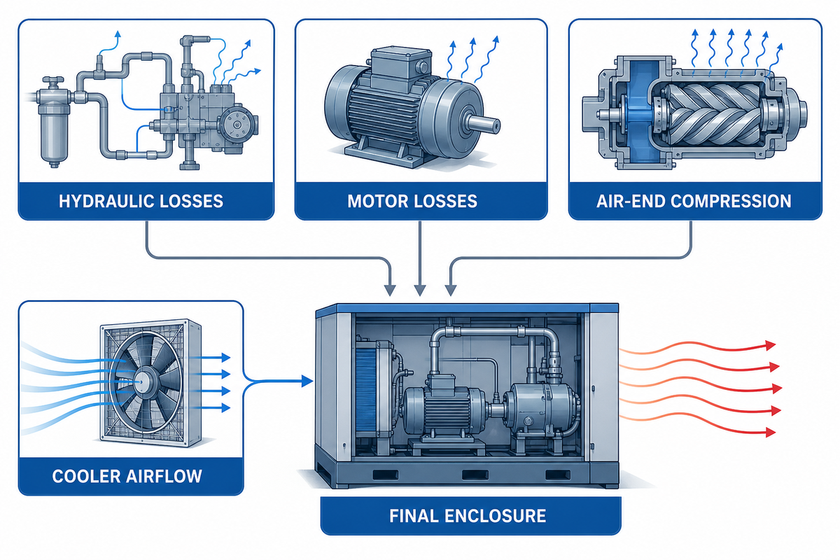
Every efficiency loss becomes heat. Hydraulic pump losses, pressure drop across valves and lines, motor losses, air-end compression, and separator or cooler restrictions all add to the thermal load. The system can meet pressure and flow on a cool morning yet exceed oil or compressor limits after a long run at high ambient temperature.
Calculate heat rejection for the worst credible continuous operating state, not only the average shift. Check hydraulic oil temperature entering the compressor, motor outlet temperature, reservoir volume and residence, cooler capacity at site ambient, fan airflow, hot-air recirculation, grille fouling, and the heat released near other vehicle equipment. If the compressor has a separate oil circuit or fan, include its airflow and shutdown behavior as well.
Mounting location can erase catalog cooling margin. Cooler placement facing an engine radiator discharge, a toolbox cavity with no exit path, road debris, or a body panel installed after commissioning can change airflow. High altitude and hot air should be evaluated as an environmental axis separate from the four operating states described later; neither a warm-load test at sea-level conditions nor a reference performance value proves operation at another site.
The same lifecycle boundary in ISO 4413 makes thermal validation part of installation, use, and maintenance, not an isolated cooler purchase.
| Thermal observation | Possible mechanism | Measurement before changing parts |
|---|---|---|
| Hydraulic oil heats rapidly with compressor on | High pressure drop, excessive bypass, undersized cooler, overload | Supply/return pressure and temperature, flow, cooler inlet/outlet air |
| Temperature normal at first, high after body is closed | Air recirculation or blocked ventilation | Ambient and cooler-inlet air with final panels installed |
| Only case-drain temperature rises | Motor leakage, housing restriction, or high load | Case flow, case pressure, motor differential pressure, speed |
Coordinate Host-Machine Loads and Control Logic
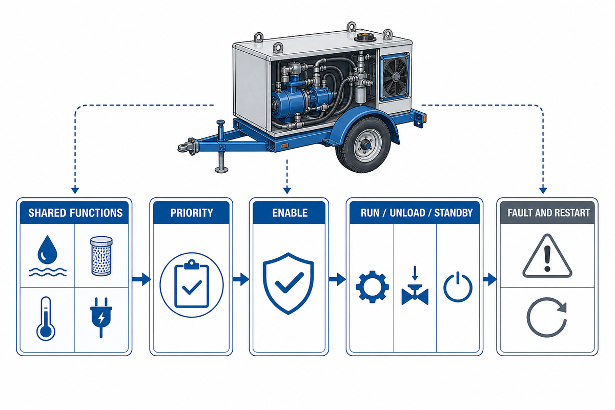
Mobile hydraulic systems rarely serve the compressor alone. Cranes, stabilizers, booms, winches, steering, cooling fans, or other functions may share pump capacity. Create an operating-mode matrix showing which functions can run together, which have priority, the minimum engine speed, and what the control system should do if hydraulic power or cooling is insufficient. The truck compatibility checker can capture the initial vehicle constraints, but branch measurements under simultaneous load remain the acceptance evidence.
Define enable, run, unload, standby, and fault states. The compressor should receive a clear demand signal and shouldn’t repeatedly load and unload because of a poorly located pressure sensor or undersized receiver. Emergency stop, host interlock, overtemperature, separator or discharge protection, overspeed, low oil, fan failure, and other functions must follow the selected package instructions and the site’s risk assessment.
Also define restart behavior after power loss or an interlock. Automatic restart may create unexpected pneumatic and hydraulic movement. Control review should cover who can reset a fault, whether stored air remains, which valve returns to a safe state, and how a technician proves that energy can’t reaccumulate during service.
Documenting those states against the hydraulic-system lifecycle requirements in ISO 4413 helps keep the control narrative attached to the actual valves, sensors, energy sources, and maintenance tasks.
Commission Across Four Operating States, and a Separate Environmental Axis
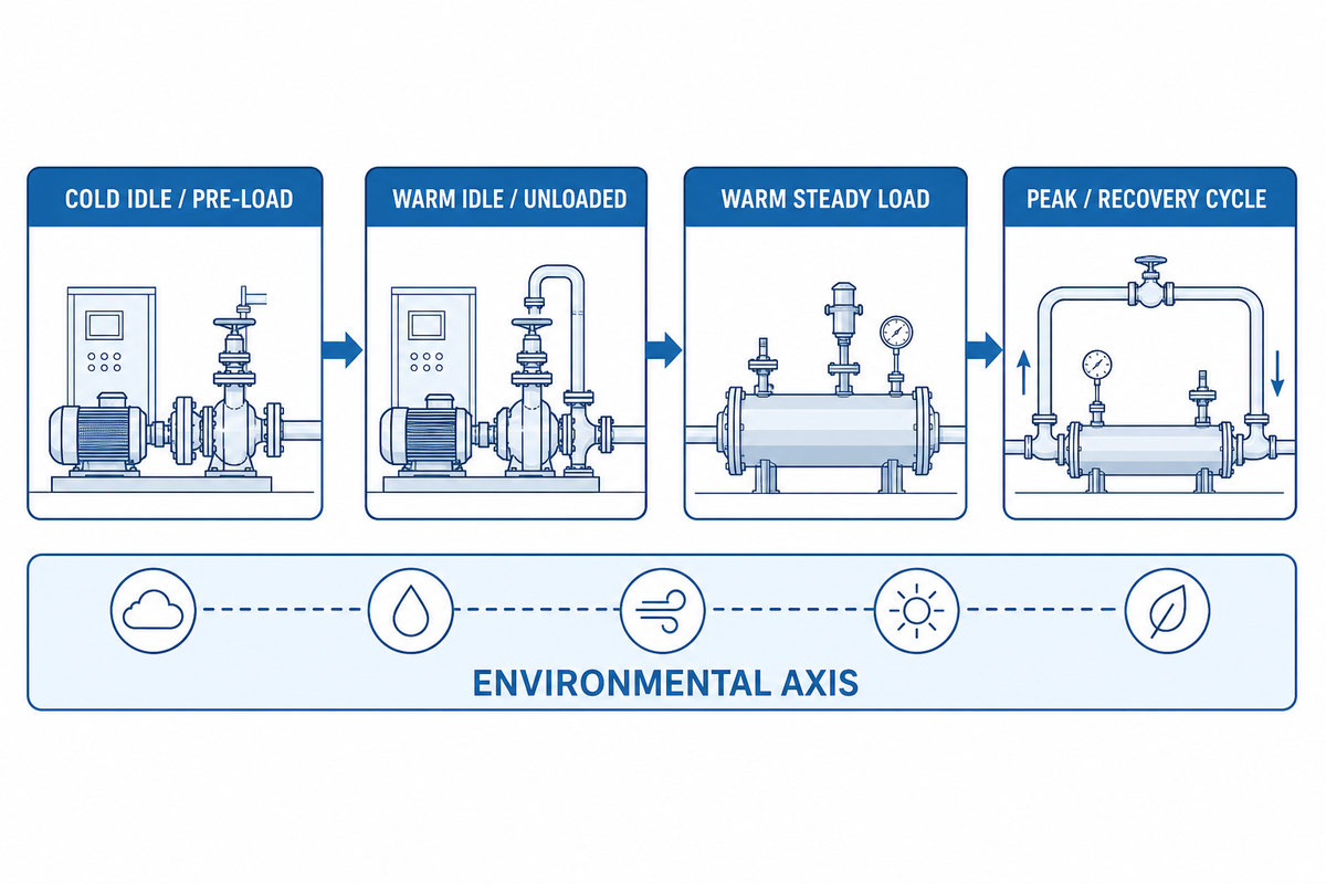
Commissioning should show how the completed installation behaves, not merely that the compressor turns. The current Gardner Denver commissioning example uses a sustained operating period with readings taken at intervals; that measurement method is useful, but its times and limits remain product-specific. Use the selected compressor, hydraulic motor, and host-machine instructions as the acceptance basis.
1. Cold idle / pre-load
Confirm fluid level and grade, rotation, valve position, hose routing, case-drain path, cooler airflow, guards, leaks, instruments, and control states. Record cold viscosity context and do not load a package outside its cold-start instructions.
Confirm fluid level and grade, rotation, valve position, hose routing, case-drain path, cooler airflow, guards, leaks, instruments, and control states. Record cold viscosity context and do not load a package outside its cold-start instructions.
2. Warm idle / unloaded
Bring the system to the defined warm condition. Record supply, return, and case pressure; flow; motor speed; hydraulic temperature; compressor temperature; noise; vibration; and unloaded control behavior.
Bring the system to the defined warm condition. Record supply, return, and case pressure; flow; motor speed; hydraulic temperature; compressor temperature; noise; vibration; and unloaded control behavior.
3. Warm steady load
Run the representative continuous air demand. Record pressure and flow at the compressor and at the tool, temperatures at timed intervals, hydraulic differential pressure, speed, current control state, and cooler inlet air.
Run the representative continuous air demand. Record pressure and flow at the compressor and at the tool, temperatures at timed intervals, hydraulic differential pressure, speed, current control state, and cooler inlet air.
4. Peak / recovery cycle
Exercise the approved intermittent peak and receiver recovery pattern. Verify pressure recovery, load/unload stability, simultaneous host functions, relief behavior, speed control, alarms, and absence of damaging thermal accumulation.
Exercise the approved intermittent peak and receiver recovery pattern. Verify pressure recovery, load/unload stability, simultaneous host functions, relief behavior, speed control, alarms, and absence of damaging thermal accumulation.
Evaluate ambient temperature, altitude, humidity, dust, vehicle-body configuration, ventilation, and inlet-air reference conditions as a separate axis across the relevant operating states. A single “passed at full load” result can hide a cooling failure at high ambient, a density change at altitude, or a restriction created by the final enclosure.
Acceptance records should identify instrument, location, unit, calibration status, operating state, ambient condition, limits, results, and approver. Where a value has no approved limit, mark it as a baseline rather than inventing a pass/fail number.
An illustrative register row might read 20 gpm, 2,150 psi inlet, 150 psi outlet, 2,400 rpm, 75 °C hydraulic oil, 32 °C cooler-inlet air, 100 psi receiver pressure, and 40 CFM delivered flow. To show how the environmental axis stays attached, a purely hypothetical four-row log could label 25 °C ambient / 30 °C oil at 1,000 rpm, 32 °C / 60 °C at 1,800 rpm, 32 °C / 75 °C at 2,400 rpm, and 40 °C / 82 °C at 2,400 rpm. Sample duration fields might read 5 min, 15 min, 45 min, and 10 min within an 8 hr shift. Every number in this paragraph demonstrates record format only; none is a target, product specification, or acceptance limit.
Use the 5-Channel Symptom-to-Measurement Triage Map
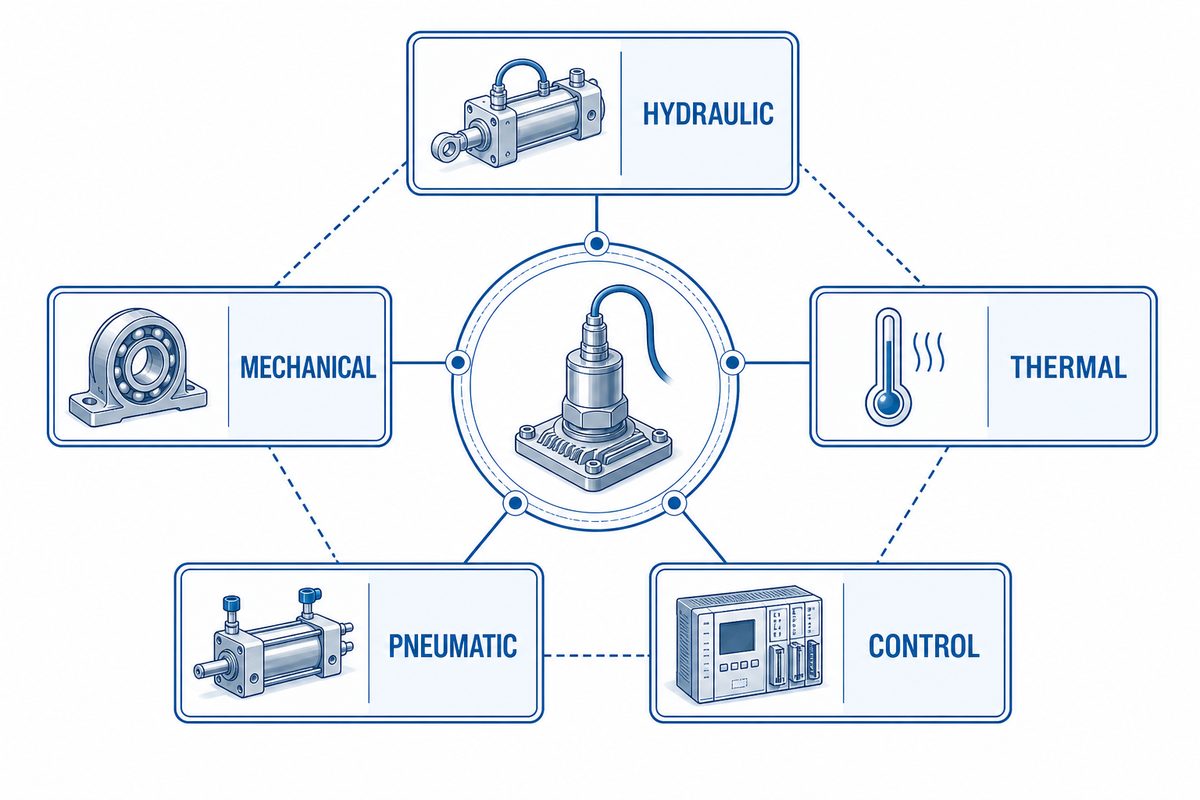
Parts swapping obscures the energy path. The 5-Channel Symptom-to-Measurement Triage Map starts with synchronized hydraulic, mechanical, thermal, pneumatic, and control readings. Stop and follow the approved safe-shutdown procedure for containment loss, a damaged hose, abnormal speed, rapidly rising temperature, severe vibration, fire risk, or any condition outside the manufacturer or site limit.
| Symptom type | Measure first | Likely branches | Do not assume |
|---|---|---|---|
| Low air flow and low motor speed | Hydraulic flow, motor rpm, valve command, engine rpm | Insufficient pump flow, priority conflict, control restriction, leakage | Higher relief pressure will restore speed |
| Low air pressure with normal motor speed | Air flow, tool pressure, inlet restriction, leaks, load/unload state | Excess demand, distribution loss, air-end or separator condition, control issue | The hydraulic motor is necessarily undersized |
| High hydraulic pressure, low speed | Supply and return pressure, flow, case pressure, shaft condition | Mechanical load, return restriction, motor distress, cold oil | Supply pressure alone equals useful differential pressure |
| Compressor or hydraulic oil overheats | Temperatures over time, cooler air, pressure drop, duty cycle | Overload, bypass loss, blocked cooler, recirculation, low oil, wrong viscosity | A larger reservoir alone solves continuous heat load |
| Case pressure or case flow increases | Case pressure/flow at specified point, return pressure, temperature | Drain restriction, motor wear, excessive load, wrong plumbing | The drain can share any convenient return |
| Speed hunts during load/unload | Flow-control command, pressure signal, receiver cycle, host loads | Control tuning, priority interaction, sensor location, unstable demand | The air end itself is the only cause |
| Tool pressure low, receiver pressure normal | Pressure at receiver and tool while flowing, hose size, coupler drop | Distribution restriction, regulator setting, hose length, leak | Compressor capacity is necessarily low |
| Air output falls as filters load | Inlet vacuum or differential pressure, service indicator, ambient dust | Inlet restriction, separator restriction, wrong element, poor service access | The hydraulic circuit changed |
| New noise or vibration after installation work | Mounting torque, alignment, hose contact, motor speed, baseline vibration | Loose mount, pipe strain, contact resonance, overspeed, coupling condition | Normal air-end noise explains every change |
One field report in which pressure fell from about 100 psi to about 30 psi before hydraulic flow was checked is a useful caution, not a diagnostic rule. Forum evidence can suggest a measurement sequence, but it can’t establish a failure cause for another machine. Treat every symptom as a hypothesis until synchronized readings and inspection support it.
The coupled variables documented in the Danfoss motor technical information reinforce why speed, differential pressure, flow, efficiency, and case condition should be read together during diagnosis.
Maintain Trends and Isolate Both Hydraulic and Pneumatic Energy
Maintenance intervals must come from the installed compressor, hydraulic motor, host system, fluid, filters, environment, duty, and site policy. The current VMAC hydraulic-driven-compressor manual uses a 500-hour interval for certain product tasks, but that’s a model-specific example, not a universal interval for hydraulic air compressors. Build the schedule from the documents delivered with the selected equipment.
Trend air flow and pressure, hydraulic supply and return pressure, case pressure or flow, motor speed, oil temperatures, cooler condition, filter indicators, contamination code, leaks, vibration, and control faults. Compare readings under an identical duty and ambient condition. Movement from baseline is more informative than a single number without context.
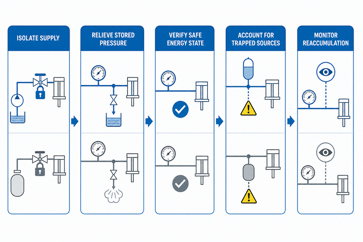
Service creates a multi-energy problem. OSHA 29 CFR 1910.147 identifies hydraulic and pneumatic energy among hazardous energy sources. Where that U.S. rule applies, the energy-control procedure must isolate sources, dissipate or restrain stored energy, verify isolation, and check for the possibility of reaccumulation. The governing site procedure and local law may add requirements.
- Shut down and isolate the host prime mover and hydraulic supply using the approved procedure.
- Relieve or restrain pressure in supply, return, case, compressor, receiver, and downstream air lines.
- Verify zero or safe energy state with the approved instruments and try procedures.
- Account for accumulators, elevated loads, check valves, trapped oil, hot surfaces, automatic restart, and receiver pressure.
- Monitor for reaccumulation if thermal change, leakage, gravity, or connected equipment can restore pressure.
Complete the Hydraulic-to-Air Integration Ledger
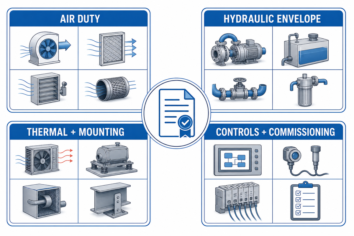
The Hydraulic-to-Air Integration Ledger keeps a project from approving the air side and hydraulic side in separate conversations. Use it as a controlled handoff among fleet, mechanical, hydraulic, electrical, controls, safety, procurement, and compressor-supplier teams.
Integration ledger fields
- Tool pressure, flow, overlap, and duty cycle
- Air-quality class or point-of-use limits
- Receiver volume and approved pressure ratings
- Hydraulic flow across engine-speed range
- Motor inlet, outlet, and case-pressure limits
- Motor displacement and permitted speed range
- Available differential pressure under shared loads
- Relief, priority, flow-control, and unload logic
- Fluid grade, viscosity range, and cleanliness target
- Supply, return, and case-drain hose details
- Reservoir and cooler performance at site ambient
- Mounting, ventilation, guarding, and service access
- Four-state commissioning results
- Environmental and reference-condition basis
- Alarm, shutdown, restart, and isolation behavior
- Documented owner for every unresolved field
Unknown values should stay marked unknown. Nominal numbers borrowed from a different vehicle, motor, climate, or tool can create a false pass. Each field needs its source, date, units, operating condition, limit, and responsible approver.
The ledger also creates the lifecycle record expected by the system-level approach in ISO 4413: design assumptions can be checked again after installation, modification, commissioning, or a duty change.
Keep Standards and Safety Claims Inside Their Actual Scope
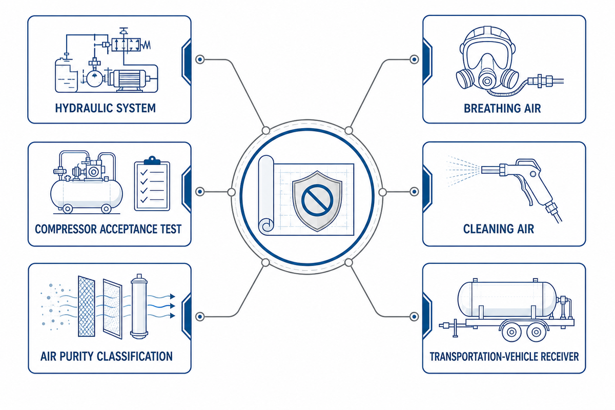
Standards change, and titles do not establish automatic compliance. At the time of this update, ISO lists ISO 4413:2010 as current. ISO 1217:2009 and ISO 8573-1:2010 remain published but are shown as due for revision, with new work items in development. ISO 4406:2021 was confirmed in 2026. Before a purchase or acceptance test, confirm the current edition, contract requirement, jurisdiction, and any more specific equipment standard.
Air quality needs an end-use definition. ISO 8573-1 classifies contaminants such as particles, water, and oil in compressed air, but a class designation needs measurement points and agreed test methods. Ordinary service air is not breathing air. OSHA 29 CFR 1910.134 contains separate U.S. requirements for breathing gas used with atmosphere-supplying respirators; a general compressor guide cannot qualify an installation for that use.
For compressed-air cleaning in U.S. workplaces, OSHA 29 CFR 1910.242(b) limits compressed air used for cleaning to less than 30 psi and requires effective chip guarding and personal protective equipment. That provision doesn’t mean every pneumatic tool should run below 30 psi; it applies to cleaning use.
Receiver requirements also depend on equipment and jurisdiction. OSHA’s 29 CFR 1910.169 air-receiver section expressly says it isn’t intended to apply to compressed-air equipment on transportation vehicles. Don’t cite that exclusion as freedom from all requirements: vehicle, pressure-vessel, transport, local, and manufacturer rules may still apply. Identify the actual governing framework for the installed receiver.
Turn the Engineering Record into a Controlled Supplier Handoff
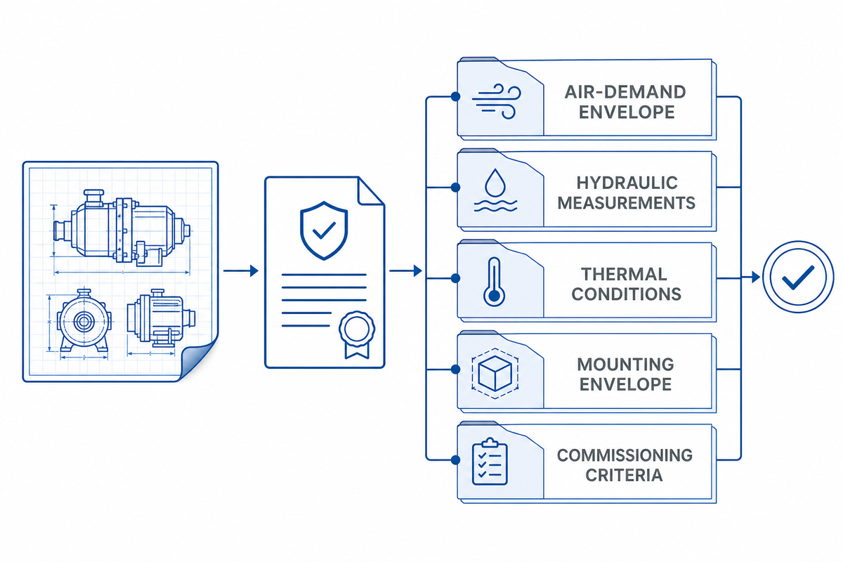
Once the ledger is complete, the supplier can evaluate a real duty instead of guessing from a vehicle description. Send the air-demand envelope, hydraulic measurements under simultaneous loads, motor and fluid details, return and case-drain design, thermal conditions, mounting envelope, control states, required air quality, commissioning criteria, and applicable standards or local rules. PanGeng’s compressor application selection guide provides a separate handoff path for projects that still need the broader compressor category defined.
This guide intentionally stops before model selection and commercial claims. For available configurations, product-specific specifications, installation review, lead time, and quotation, continue to PanGeng’s hydraulic air compressor solution page. Keep the completed integration ledger attached so the commercial discussion stays tied to measured conditions.
For the demand side of that handoff, the CAGI sizing brief provides a useful check that minimum, average, maximum, intermittent, and continuous loads haven’t been collapsed into one unsupported flow number.
Application review inputs
Prepare your air duty, hydraulic supply and return readings, ambient conditions, and available installation envelope. PanGeng can review the application boundary before product-specific recommendations are made.
Frequently Asked Questions
These concise answers retain the system, product-limit, and safety boundaries established above, including the separate breathing-air requirements in OSHA 29 CFR 1910.134.
How does a hydraulic air compressor work?
A hydraulic air compressor uses host-machine hydraulic flow to turn a motor, which drives the air end; motor speed, torque, cooling, and control limits govern the compressed-air output.
The host hydraulic pump supplies flow and pressure differential. Flow, motor displacement, and efficiency determine motor speed; pressure differential and displacement determine available torque. The air end then compresses intake air within its approved speed, temperature, pressure, and control envelope. Hydraulic and air pressures are related through power and machine design, not by a one-to-one pressure conversion.
How much hydraulic flow does an air compressor need?
Hydraulic flow depends on the selected motor displacement, target speed, efficiency, and compressor duty, so the approved package input range and measured branch flow must determine the requirement.
Do not select by a generic gallons-per-minute rule or a value copied from another vehicle. Obtain the approved input range for the actual package, then verify measured flow at the compressor branch across engine speed, oil temperature, and simultaneous host functions. The circuit must also meet differential-pressure, return-pressure, case-pressure, cooling, filtration, and speed-control limits.
Can I increase hydraulic pressure to get more compressed air?
Increasing hydraulic pressure is unsafe unless the complete motor and compressor envelope permits it; extra pressure may add heat or overload components without correcting low flow or speed.
Flow primarily affects speed, while pressure differential provides torque against load. Raising a relief setting may add heat or overload hoses, valves, the motor, coupling, or air end; it may not correct low flow. Measure supply and return pressure, hydraulic flow, motor speed, case pressure, oil temperature, and air output before changing an approved setting.
Why does a hydraulic air compressor overheat?
A hydraulic air compressor can overheat from overload, excessive pressure drop, bypass loss, inadequate cooling, hot-air recirculation, or duty beyond the approved continuous operating envelope.
Trend hydraulic inlet and outlet pressure and temperature, case conditions, compressor temperatures, cooler inlet air, motor speed, air demand, and time. Check the final enclosure and simultaneous host loads. A larger oil tank may slow the temperature rise but does not remove a continuous heat load.
Does every hydraulic motor need a case drain?
Follow the exact motor and compressor-package instructions.
Many piston-motor arrangements require a low-restriction case-drain path, while architectures and permissible housing pressures differ. Never omit, plug, combine, or reroute a required drain based on another model. Verify case pressure at the specified point during cold, warm, steady-load, and peak states.
Can a hydraulic air compressor supply breathing air?
Do not treat ordinary service air as breathing air.
Breathing-gas systems for atmosphere-supplying respirators have separate source, quality, monitoring, alarm, maintenance, and regulatory requirements. An ordinary compressor, dryer, filter, receiver, or general air-purity statement does not qualify an installation for respirator use. Oil carryover, carbon monoxide, moisture, source location, monitoring, couplings, and backup provisions may all require specific control. The intake must remain protected from engine exhaust and other contamination, while alarms and sampling need defined locations and response authority. A temporary filter added to a service-air outlet cannot establish those safeguards. Use a breathing-air system and written program designed and approved for the actual respirator duty and jurisdiction; have the responsible safety professional verify the applicable law, equipment, test method, records, and emergency plan before use.
References & Sources
The following primary and technical sources support the standards, calculations, demand, installation, commissioning, and safety boundaries in this guide. Product-manual values discussed in the research were treated as product-specific examples and weren’t transferred as PanGeng ratings.
- ISO 4413:2010 hydraulic fluid-power system requirements and lifecycle scope.
- ISO 1217:2009 displacement-compressor acceptance tests and revision status.
- ISO 4406:2021 coding solid-particle contamination in hydraulic fluid.
- ISO 8573-1:2010 compressed-air purity classes and revision status.
- SAE J1273_202110 recommended practices for hydraulic hose assemblies.
- CAGI Compressed Air System Sizing demand profile and storage boundaries.
- Danfoss MP1 motor technical information flow, speed, differential pressure, torque, power, and case-condition relationships.
- Gardner Denver commissioning checklist sustained-run measurement method as a product-specific example.
- OSHA 29 CFR 1910.147 control of hazardous energy.
- OSHA 29 CFR 1910.134 respiratory protection and breathing-gas safeguards.
- OSHA 29 CFR 1910.242 compressed air used for cleaning.
- OSHA 29 CFR 1910.169 air-receiver scope and transportation-vehicle exclusion.
How this guide is framed
Anhui PanGeng Gas Compressor Co., Ltd. manufactures industrial compressor equipment. This educational guide deliberately avoids model rankings, product performance tables, prices, certifications, and universal operating limits. Its purpose is to help fleet, engineering, maintenance, safety, and procurement teams create a measured integration record before moving to a separate product-specific review.