Get in Touch with Pangeng

Reciprocating Hydrogen Compressor Guide: Duty & Evidence

Contents
show
Engineering guide · Reviewed August 2026
Engineering a Reciprocating Hydrogen Compressor Duty
A Reciprocating Hydrogen Compressor Guide is an engineering map for teams that have already shortlisted piston-type reciprocating compression and now need to document duty, staging, leakage control, monitoring, maintenance, interfaces, and acceptance evidence before package configuration. It begins with a complete gas and demand envelope, then connects that envelope to each engineering decision without reopening the broader compressor-family selection handled by dedicated selection and comparison guides.
1. How Does a Reciprocating Hydrogen Compressor Work?
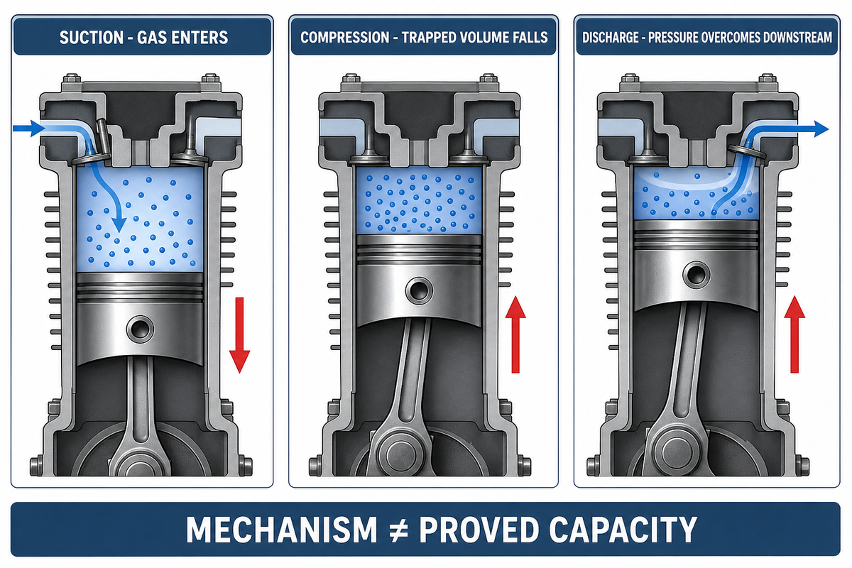
A reciprocating hydrogen compressor uses linear piston or diaphragm motion to reduce a trapped gas volume and raise its pressure. In the piston-type machine discussed here, the piston moves inside a cylinder while pressure-actuated suction and discharge valves control flow. The U.S. Department of Energy uses the wider reciprocating definition, so a project record should state whether it means a piston machine, a diaphragm machine, or the broader motion family.
That is how piston machines compress hydrogen by reducing the volume; the cycle raises compressor pressure without changing hydrogen molecules or proving capacity. Among positive displacement compressors, a piston compressor normally converts electric-motor rotation through a crank and connecting rod or related motion train. That movement lets the compressor cylinder compress the gas on a repeating cycle. The mechanism explains reciprocating compression; it doesn’t establish compressor performance for a particular hydrogen application.
The cylinder cycle has three main flow states. During suction, falling cylinder pressure allows the inlet valve to admit gas. During compression, the valves are nominally closed while the piston reduces volume. During discharge, cylinder pressure rises above the downstream condition and the discharge valve opens. Gas remaining in clearance spaces then re-expands before the next intake begins. This is a positive-displacement process, but displacement isn’t the same as delivered flow.
Suction
Inlet state, valve behavior, and upstream pressure affect how much gas enters.
Compression
Volume falls while leakage, heat transfer, and gas properties influence the pressure path.
Discharge
The valve opens against the actual downstream pressure and system resistance.
Clearance volume, valve losses, ring bypass, packing behavior, gas temperature, pressure ratio, speed, and capacity control can all move actual capacity away from a simple swept-volume estimate. Hydrogen’s low molecular weight also makes leakage control important, but the machine-family name doesn’t supply an exact leakage rate. The Department of Energy overview describes tight tolerances; it doesn’t establish the delivered capacity, seal life, bearing life, or material reliability of a particular package.
This boundary matters in troubleshooting. Low flow doesn’t prove a worn ring, and a hot discharge doesn’t prove a bad valve. Changes in suction state, cooler performance, downstream restriction, valve condition, clearance arrangement, or internal bypass may produce overlapping symptoms. The first engineering task is therefore to identify the operating state in which the symptom occurred.
2. Start With the Duty Sheet: Pressure, Flow, Gas, and Demand
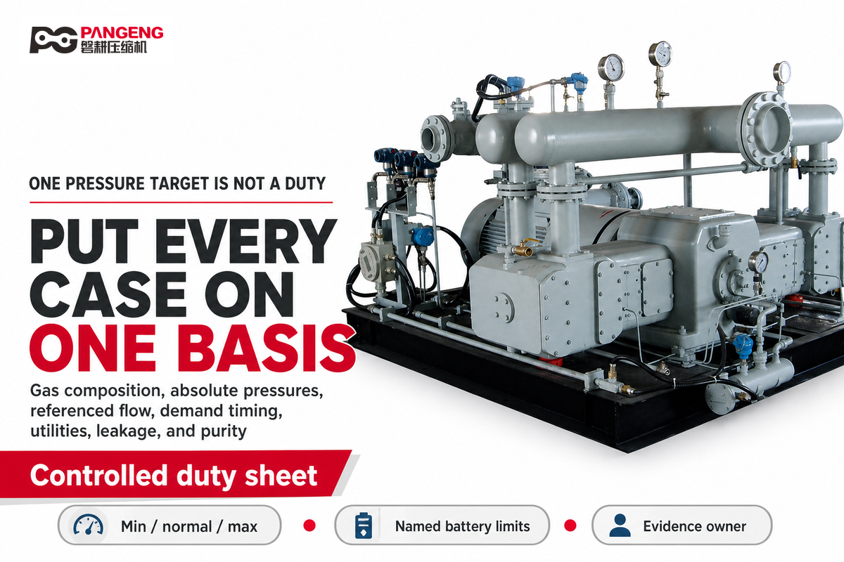
A discharge-pressure target alone isn’t a compressor duty. The same target can describe very different cylinders and packages when suction pressure, temperature, composition, referenced flow, demand pattern, cooling utility, and downstream backpressure change. Put minimum, normal, maximum, startup, recycle, and credible transient cases on one controlled sheet before debating stage count.
Write the flow rate, compressor discharge pressure, and compressor operating cases on the same basis. A high pressure target without a defined inlet state cannot produce a meaningful compression ratio. Petrochemical continuity, intermittent transfer, and storage-filling cases may share a pressure target but require different control and availability decisions.
How does hydrogen’s low molecular weight affect compressor sizing?
Low molecular weight influences density, leakage tendency, volumetric behavior, and the relationship between mass flow and normalized volume. Flow numbers without reference temperature, reference pressure, composition, suction state, and demand profile are incomplete. Actual sizing also depends on clearance, valve behavior, speed, stage inlet conditions, cooling, turndown, and acceptable leakage. Compare all cases on one declared basis, then let the responsible supplier validate capacity across the required envelope.
| Input | Record it as | Why it matters | Who confirms |
|---|---|---|---|
| Gas composition | Components, allowable variation, moisture and contaminants | Sets property, purity, materials, sealing, and hazard questions | Process owner and project engineer |
| Suction and discharge | Absolute pressure and temperature at named battery limits | Defines density, overall ratio, and interface conditions | Process owner, engineering contractor, supplier |
| Flow | Mass flow or normalized volume with its complete reference basis | Prevents incomparable flow cases and false capacity conclusions | Process owner and supplier |
| Demand pattern | Hours, starts, load steps, turndown, standby, storage behavior | Changes controls, cycling, capacity strategy, and maintenance exposure | Owner/operator and controls team |
| Utilities and ambient | Power, cooling inlet range, available flow, site temperature, elevation | Constrains thermal performance and installed package design | Site and package teams |
| Leakage and purity | Boundary, analytes, sample point, test method, duration, limit | Turns labels into measurable acceptance evidence | Process, safety, quality, and supplier teams |
Use an absolute pressure for ratio calculations. For example, a hypothetical inlet of 2 bar absolute (200 kPa) and outlet of 18 bar absolute (1.8 MPa) produce an overall ratio of 9. There’s nothing inherent in that calculation about the correct number of stages, cylinder choice, cooler distribution, or allowable discharge temperature. It just provides the team one properly based input.
A fictional record-format example
The examples below are made up to illustrate how units, cases, locations, and owners can be described; they aren’t intended to be recommendations, a Pangeng capability statement, or a sizing input for any real package. Every value in a real duty sheet needs to be replaced with the controlled data for the project.
| Input type | Minimum / normal / maximum entry | Basis or location | Owner before review |
|---|---|---|---|
| Composition | 99.8 mol% H2 and 0.2 mol% N2 | Current inlet analysis; allowable variation still open | Process owner |
| Suction pressure | 1.8 bar(a) / 2.0 bar(a) / 2.2 bar(a) | Compressor inlet battery limit | Process owner |
| Suction temperature | 20 °C / 25 °C / 35 °C | Named inlet measurement point | Process engineer |
| Required discharge | 18 bar(a) at the named outlet | Downstream requirement, not a package guarantee | Downstream owner |
| Mass flow | 60 kg/h / 100 kg/h / 120 kg/h | Dry-gas mass basis | Process engineer |
| Storage backpressure | From 12 bar(a) to 18 bar(a) | One fictional fill cycle | Storage-system owner |
| Operating pattern | 16 h/day and up to 4 starts in 24 hours | Planning scenario only | Owner/operator |
| Ambient basis | 0 °C to 40 °C at 600 m elevation | Outdoor plot assumption | Site engineering |
| Cooling-water inlet | 25 °C to 32 °C; 15 m³/h assumed | Battery-limit utility | Utilities owner |
| Electrical placeholder | 400 V, 50 Hz, 75 kW | Fictional supply basis, not a motor selection | Electrical owner |
| Utility placeholders | 6 bar(g) air, 5 bar(g) nitrogen, 38 °C return, 230 V auxiliary, 24 V control, 10 A circuit, 4 mA to 20 mA signal | Fictional interface entries; availability unconfirmed | Utilities owner |
This example reveals unresolved work. The normal pressure ratio is calculable, yet the minimum-suction case produces a different ratio. Cooling-water flow remains open. Composition variation and purity acceptance are incomplete. Storage backpressure varies during the cycle. Suppliers can now ask focused questions instead of silently assuming one steady condition.
The linked hydrogen compression pressure calculator returns a theoretical preliminary estimate from entered inlet pressure, target discharge pressure, flow, and inlet temperature. Use it as an initial analysis aid, not as a piston-package sizing decision.
3. Build the Stage and Cooling Strategy Around the Real Envelope
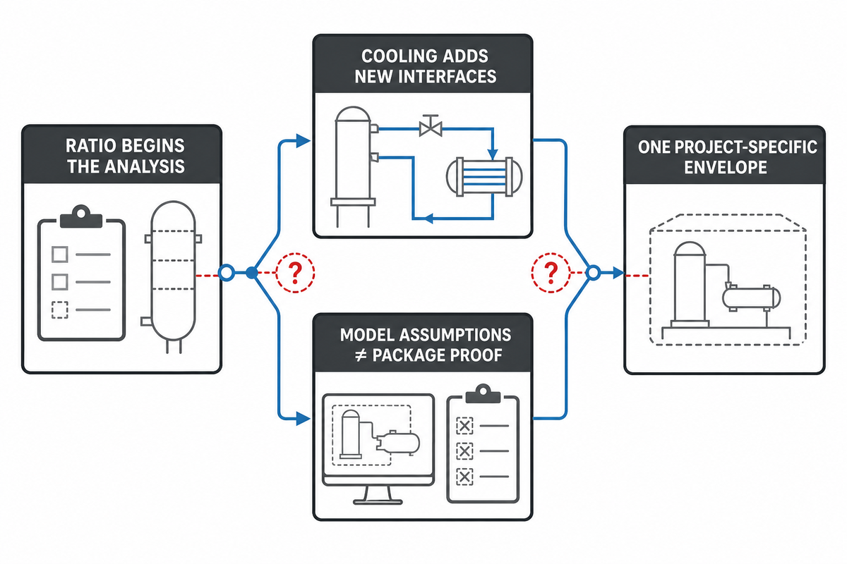
Overall pressure ratio is what begins stage analysis, not what concludes it. Peer-reviewed thermodynamic analysis arrives at equal stage ratios only under specified conditions including ideal-gas behavior, equal stage efficiencies, and no interstage head loss; changing that efficiency assumption alters the answer. That publication does not confirm rod load, valve behavior, pulsation, turndown, or the suitability of a hydrogen package. Those remain separate project and supplier checks, not direct results of the thermodynamic calculation.
Five checks after the ratio calculation
- Confirm the absolute-pressure basis and all required operating cases.
- Model gas properties and stage inlet conditions on the chosen basis.
- Check intercooling, pressure loss, utility range, and allowable temperatures.
- Check cylinder loading, rod load, valve behavior, clearance, pulsation, and turndown.
- Validate the complete envelope with the responsible package and project engineers.
Cooling links these decisions. Lower stage inlet temperature can reduce compression work and change density, but a cooler introduces pressure loss, condensate or contaminant-management questions, utility dependence, and a new control interface. The relevant temperature limit is the approved project or package limit for the actual materials, lubricant strategy, valves, seals, and operating case, not a generic value copied from a different study.
Intercooling may support lower discharge temperatures in a modeled case, but that phrase isn’t a guarantee. Cooler approach, fouling, pressure loss, ambient conditions, gas properties, and off-design flow all belong in the compressor design review.
| If this input is missing | This decision remains open | Evidence needed |
|---|---|---|
| Minimum suction pressure | Maximum overall ratio and low-density capacity case | Guaranteed boundary condition and transient profile |
| Cooling-water seasonal range | Stage inlet and discharge temperature envelope | Utility design basis, fouling allowance, cooler duty |
| Turndown and recycle cases | Capacity-control method and off-design limits | Demand timeline and controls narrative |
| Piping/pulsation boundary | Nozzle loads, pulsation treatment, and mechanical response | Connected-system model and interface ownership |
Don’t submit generic “stage ratio,” “stage count,” “pressure ceiling,” or “discharge-temperature ceiling” from this sequence. The acceptable result is a project-specific operating envelope where thermal, mechanical, sealing, piping, control, and utility constraints concur.
4. Control Leakage, Lubrication, and Contamination
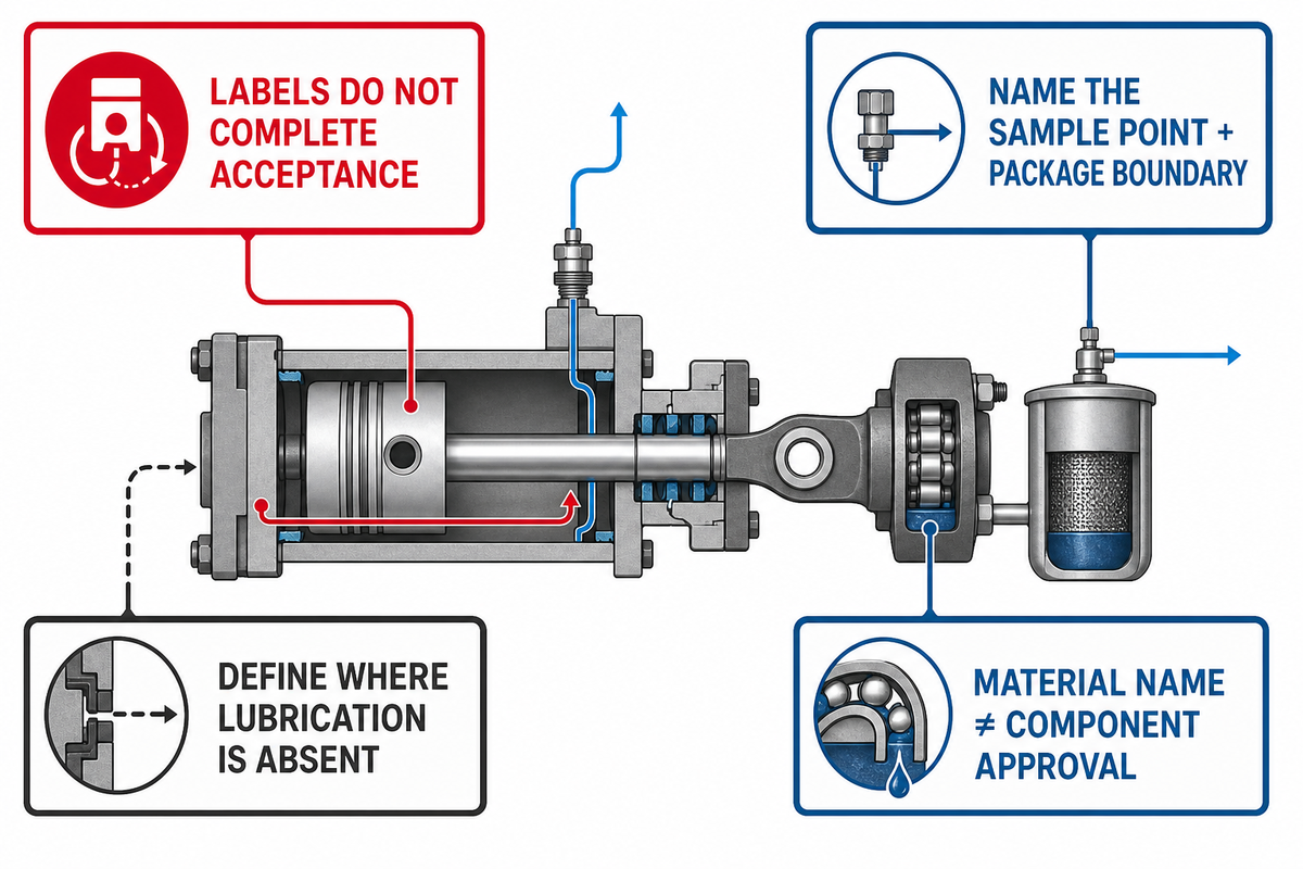
“Oil-free,” “non-lubricated,” “hydrogen-compatible,” and “leak-tight” are useful starting labels, but none defines a complete acceptance boundary. Non-lubricated cylinders can still sit in packages with lubricated running gear. Oil-free compression chambers can still have internal bypass or external leakage. Compatible alloy names do not establish the behavior of every heat, weld, surface, seal, fastener, or stressed component. That operating envelope must now be translated into sealing, lubrication, and contamination boundaries.
For non-lubricated compressors, state exactly which cylinder lubrication is absent and which bearings, crankcase systems, or auxiliaries still use lubricant. Treat “non-lubricated reciprocating” and “non-lube compressor” as shorthand, not complete package definitions. If the purity concept includes separators or oil removal systems downstream, include their sample points, operating states, maintenance products, and acceptance limits in the same evidence chain.
| Pathway | Possible consequence | Qualifying evidence | Typical owner |
|---|---|---|---|
| Valves and internal bypass | Capacity loss, changed temperatures, disturbed pressure trace | Comparable operating-state data, inspection, approved test method | Supplier and reliability team |
| Piston rings and cylinder surfaces | Blow-by, heat, reduced volumetric performance | Material/condition record, wear findings, pressure and leakage trends | Supplier and maintenance team |
| Rod packing and vents | External leakage or gas routed to a vent system | Vent boundary, routing drawing, measured flow, alarm/action basis | Package, process, and safety teams |
| Joints, drains, and instruments | Local release or air ingress under some states | Connection schedule, test record, detector coverage and inspection access | Engineering contractor and site |
| Lubricants and maintenance products | Gas contamination or downstream incompatibility | Product list, migration boundary, sample plan, downstream limit | Supplier, owner, and quality team |
| Coolers, separators, and downstream removal | Carryover, condensation, or an unverified purity assumption | Sampling location, analyte, method, limit, and operating case | Process and quality teams |
Materials evidence needs the same discipline. Sandia’s hydrogen-materials reference separates deformation behavior, fracture resistance, and fatigue resistance. Those dimensions are related, but they are not interchangeable. Record material condition, stress and environment, manufacturing and joining condition, temperature, pressure cycling, fatigue basis, inspection method, and the component to which the evidence applies. The reference does not approve an alloy for a particular compressor.
Purity evidence should name the sample point and the package boundary. If a downstream instrument reports compliant gas, ask which operating state was sampled, which contaminants were measured, and whether the result includes maintenance products, drains, separators, and connected piping. A marketing label cannot replace that chain.
If contamination control drives the compressor-family decision, use the dedicated diaphragm compressor vs reciprocating compressor comparison. This guide keeps the discussion at the evidence boundary rather than declaring one technology universally better.
5. Define System Interfaces for a Shortlisted Reciprocating Package

Once piston-type reciprocating compression is on the shortlist, interface review must test it against changing inlet pressure, available flow, downstream resistance, permissives, trips, and utility conditions. Electrolyzer output may vary with production and plant controls. Storage backpressure changes as inventory changes. Continuous processes may value availability and controlled transitions differently from batch transfers. The interface record must describe these states, not just label the application.
Hydrogen production plants linked to renewable energy may see variable hydrogen production, while green hydrogen storage can impose a changing hydrogen storage pressure. Data from hydrogen fueling stations should not be transferred automatically to a refinery or continuous process: the population, duty cycle, control ownership, and maintenance environment may differ.
When hydrogen produced by hydrogen generation equipment feeds a hydrogen fuel cell, storage, hydrogen makeup, or a process header, compare the supply profile with demand for hydrogen. A stream containing hydrogen and carbon dioxide also requires its full composition and separation boundary rather than a pure-hydrogen assumption.
| Scenario | Interface questions | Evidence to preserve |
|---|---|---|
| Electrolyzer-linked production | How do output variation, minimum flow, buffer volume, purity release, and start permissives interact? | Time-based supply profile, control ownership, buffer assumptions, startup and shutdown narrative |
| Storage filling or transfer | How does changing backpressure affect ratio, flow, temperature, recycle, and end-of-fill control? | Storage pressure timeline, demand cycle, isolation and relief interfaces, acceptance states |
| Refinery, chemical, or ammonia process | What continuity, composition variation, turndown, redundancy, and trip response does the process require? | Operating cases, continuity philosophy, process interlocks, restart responsibility, utilities |
A Department of Energy ARIES research-system account shows why dynamic coordination belongs in the review. Supervisory controls communicated with subsystems, including the compressor, and with safety valves and relays; commissioning and supplier tuning affected operation. The specific research architecture and values do not transfer to a commercial plant. The transferable lesson is that control ownership, transient states, safety-device interfaces, and commissioning status need named evidence owners.
Where the U.S. process safety management regulation in 29 CFR 1910.119 applies, the covered employer must maintain process safety information and operating procedures, including safe limits and shutdown responsibility. That is an applicability-qualified owner/operator duty. It is not a universal rule for every hydrogen project and not proof that a compressor supplier owns the whole process-control or safety file.
If the compressor family has not yet been shortlisted, stop here and use the hydrogen gas compressor selection guide or review the hydrogen compressor options hub. Return to this guide after a reciprocating option has entered the candidate set; no one package should be described as serving the entire hydrogen value chain without a condition-complete duty review.
6. Monitor the Operating Envelope Before Blaming a Component
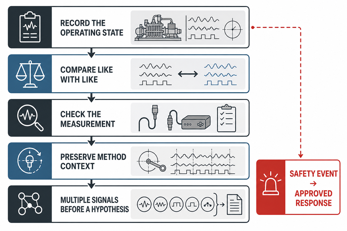
Condition data becomes useful only when it’s tied to operating state. Vibration readings without load and speed, temperatures without pressure and cooling state, or vent-flow observations without the applicable gas case can mislead an investigation. The same component may produce different signals at startup, full load, recycle, or changing storage backpressure. That condition-complete duty provides the context for each monitoring point.
Operating-state evidence sequence
- Record load, speed, pressures, temperatures, gas state, control mode, and timestamp.
- Compare the observation with a baseline from a genuinely comparable state.
- Repeat the measurement and check instrument quality before interpreting a change.
- Preserve crank-angle, phase, location, and reference context where the method depends on them.
- Form a component hypothesis only after multiple signals point in a consistent direction.
Pair evidence that tests different explanations. Reduced capacity plus a changed cylinder pressure trace may support a valve or leakage hypothesis; reduced capacity alone doesn’t. Rising packing vent flow plus a repeatable comparable-state trend may justify inspection planning; one reading without a defined basis doesn’t. High discharge temperatures should be reviewed with suction state, ratio, cooling, valve behavior, and instrument condition.
Hydrogen detection has its own context requirement. H2Tools states that “Gas detection instrument location is critical to proper functioning.” Detector location, ventilation pattern, possible release points, alarm logic, source isolation, safe-mode response, and manual reset belong to a coordinated facility design. A detector alarm is not a machine diagnosis, but it is a safety event that must follow the approved response.
Monitoring narrows hypotheses; it doesn’t prove root cause on its own. Preserve the baseline and first-out sequence so the investigation can distinguish a real process change, an equipment change, a sensor problem, and a control-interface problem.
7. Plan Maintenance and Troubleshoot by Symptom, Not Guesswork
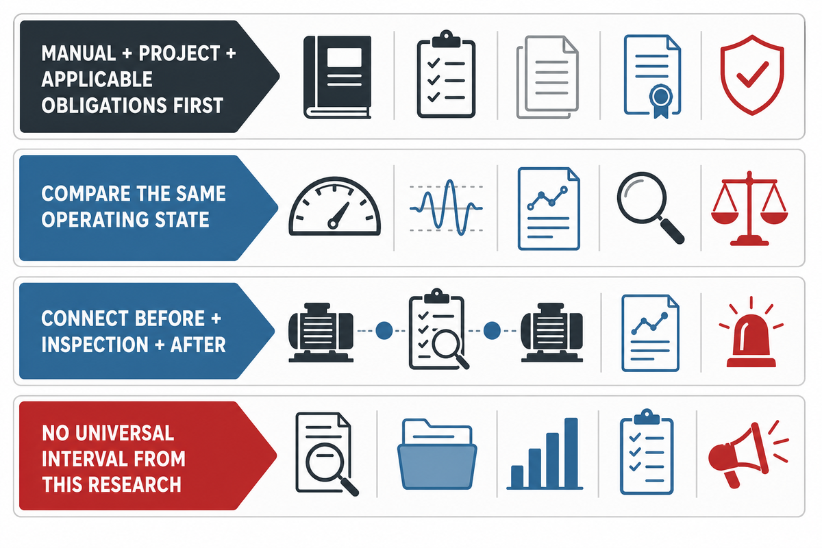
The reviewed sources did not establish one maintenance interval for every hydrogen reciprocating duty, so this guide does not supply one. The monitoring baseline and first-out sequence from the preceding step then become maintenance evidence. Begin with the approved package manual, project requirements, applicable regulation, and the owner’s maintenance program. Then use operating history and condition evidence to decide whether a planned action should be brought forward, left on schedule, investigated, or escalated.
| Symptom | Collect first | Do not conclude yet | Escalation evidence |
|---|---|---|---|
| Lower delivered flow | Suction state, discharge pressure, speed, control position, comparable baseline | “The rings failed” | Repeatable trend, pressure/temperature evidence, approved inspection |
| Higher discharge temperature | Ratio, inlet temperature, cooler utility, flow, valve and instrument context | “The discharge valve leaked” | Comparable-state pattern plus direct test or inspection |
| Changed vibration or pulsation | Location, phase, speed, load, pressure, piping and foundation state | “The cylinder is mechanically damaged” | Repeatable phase-referenced data and qualified mechanical review |
| Rising vent or detected leakage | Measurement basis, gas state, route, detector status, maintenance history | “A single packing element is the cause” | Approved safety response, repeatable quantified evidence, inspection |
| Repeated trip | First-out record, permissives, setpoints, instrument checks, operating case | “Restarting will clear a nuisance trip” | Approved investigation and authorized return-to-service decision |
Track pressures, temperatures, vibration, and component observations against a comparable operating state, as the Baker Hughes examples do. This guide also asks the maintenance record to connect the pre-work symptom, inspection, replaced-part condition, and post-work baseline; that documentation step is an original workflow, not a published spares result or universal interval.
Practitioner discussions can reveal useful symptom vocabulary and competing hypotheses, but they aren’t authority for a cause or interval. Direct measurements, controlled inspections, the approved manual, applicable obligations, and competent review remain the decision basis.
For interval design, predictive maintenance, and failure-prevention work beyond this guide’s evidence-capture boundary, continue with the hydrogen compressor maintenance planning guide.
8. Define Safety, Standards, and Acceptance Evidence
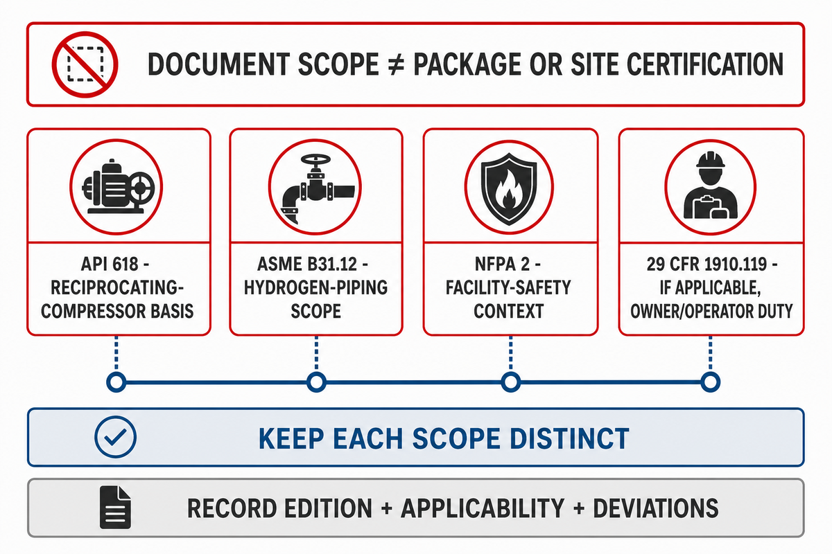
A standard name can establish a document scope; it cannot certify an unidentified package or site. The approved manual and applicable obligations from the maintenance review belong in the project’s acceptance-document set; they do not define the scope of API 618. API Standard 618’s public title associates it with reciprocating compressors for petroleum, chemical, and gas-industry services. The reviewed API page did not expose an edition, so this guide does not state one. The project specification must identify the adopted edition, purchaser requirements, and agreed deviations.
What is API 618 and why does it matter for hydrogen compressors?
API 618 is an industry standard associated with reciprocating compressors used in petroleum, chemical, and gas-industry services. Its project relevance depends on the specified edition, scope, purchaser requirements, and deviations. Naming it does not certify the complete hydrogen package, connected piping, site ventilation, gas detection, electrical classification, or jurisdictional compliance. Buyers should request a clause-applicability and deviation record and keep package evidence separate from site-level approvals.
| Document | It can establish | It does not establish alone | Project evidence still needed |
|---|---|---|---|
| API 618 reference | Specified reciprocating-compressor document basis | Whole-site hydrogen compliance or an unstated supplier certification | Edition, applicability, purchaser additions, deviations, tests |
| ASME B31.12 reference | Hydrogen-piping scope through the joint connecting piping to equipment | Qualification of the compressor equipment itself | Adopted edition, piping design record, joint/interface responsibility |
| NFPA 2 reference | Hydrogen-technology safety document context; official page lists 2026 current edition | Installed-system acceptance without applicability and jurisdiction review | Edition/amendment record, facility design, approvals and tests |
| 29 CFR 1910.119, if applicable | Covered-employer process-safety information and procedural obligations | Universal applicability or compressor-vendor ownership of the process file | Coverage determination, owner/operator program, qualified legal/safety review |
The compressor, hydrogen piping, and site-control documents have distinct scopes, but their interfaces are interdependent. At a physical boundary, preserve the joint, design-condition, material, test, and approval records. At a control boundary, preserve discharge-pressure protection, relief and isolation, emergency shutdown, classified electrical basis, internal and external leakage monitoring, detector actions, ventilation, trips, reset philosophy, and witness records.
Detector placement and ventilation require project analysis. H2Tools connects detection to actions such as isolation, alarm, safe mode, ventilation where appropriate, and manual reset. Therefore a package signal list should be checked against the facility cause-and-effect record rather than reviewed in isolation.
If a search result is labeled “Reciprocating hydrogen compressor guide PDF,” “Atlas Copco hydrogen compressor,” or “NEUMAN & ESSER compressor,” treat it as model- and revision-specific until the document itself proves otherwise. Do not transfer its limits or procedures to a Pangeng project or unidentified package without a controlled applicability review. Likewise, 200 bar is only a pressure phrase until the document defines the absolute or gauge basis, location, gas state, and operating case.
For a buyer-facing document sequence, use the API 618 reciprocating compressor checklist. It remains a preparation aid, not a compliance determination or replacement for the controlling documents.
9. Use the Hydrogen Envelope Open-Item Register Before the RFQ
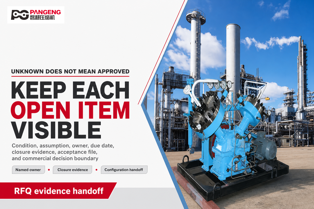
A strong RFQ does more than gather numbers. It demonstrates which conditions are approved, which assumptions remain, who owns each interface, what acceptance evidence is necessary, and which commercial decisions still fall to supplier review. The Hydrogen Envelope Open-Item Register makes those boundaries visible.
Hydrogen Envelope Open-Item Register
1. Duty states
Gas, absolute pressures, temperatures, referenced flow, normal and transient cases.
2. Thermal and mechanical inputs
Cooling range, ambient, turndown, stage assumptions, piping and pulsation boundary.
3. Leakage and purity
Boundary, vent routing, contaminants, sample points, methods, limits, evidence owner.
4. System interfaces
Upstream profile, downstream demand, controls, isolation, relief, shutdown, restart.
5. Acceptance file
Applicable documents, editions, deviations, tests, trips, witness and approval records.
6. Open decisions
Unknowns, assumptions, exclusions, responsible party, due date, closure evidence.
Mark an unknown as open rather than hiding it in a note. If a reference flow lacks its basis, assign an owner to confirm it. If a leakage limit lacks a measurement boundary, keep acceptance open. If the site has not chosen the shutdown hierarchy, do not suggest that a standard package logic has achieved it.
The same rule applies to total cost of ownership. Purchase price, energy, planned maintenance, spares, downtime potential, utilities, inspection, and site integration need project data. General guides can specify those cost categories, but they cannot publish a universal savings or lifecycle ranking.
Once this evidence-ready handoff is complete, use the reciprocating hydrogen compressor configuration and quotation page. That page is the commercial owner; this guide deliberately does not publish any Pangeng model, performance range, price, delivery promise, or project-specific selection.
Take the evidence register to a configuration review
Prepare gas composition, absolute pressures, referenced flow, operating states, utilities, leakage and purity limits, interfaces, and necessary evidence.
For company background and the commercial review route, see the Pangeng technical team profile. First-party company information remains an attributed brand context, not independent performance evidence.
10. Frequently Asked Questions
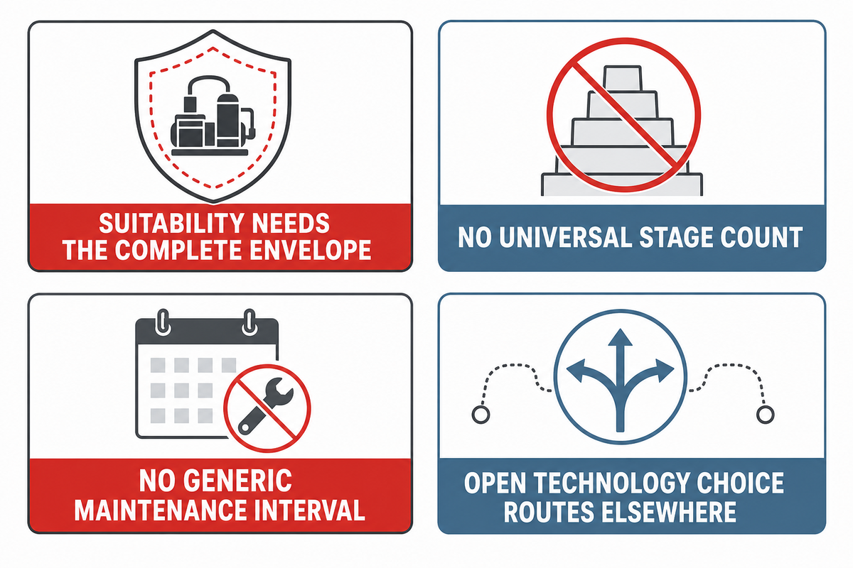
Company background does not replace the duty-boundary and evidence rules; the questions below carry those rules into common buyer decisions.
Can reciprocating compressors handle pure hydrogen?
Yes, reciprocating machines are used in hydrogen service, but the compressor-family name isn’t a universal approval. Suitability depends on gas composition, absolute suction and discharge conditions, referenced flow, duty cycle, lubrication and contamination limits, materials, sealing and venting, cooling, controls, and project requirements. “Pure hydrogen” also needs a defined composition and sampling point. The selected cylinder and package must be verified against the complete operating envelope and the project’s measurable leakage, purity, safety, and acceptance boundaries.
How does hydrogen’s low molecular weight affect compressor sizing?
Low molecular weight affects density, leakage tendency, volumetric behavior, and the relationship between mass flow and normalized volume. Flow values need reference temperature, reference pressure, composition, and suction state. Capacity also depends on clearance, valve behavior, speed, stage conditions, cooling, turndown, and leakage. Keep every flow on a declared basis and require supplier validation across all duty cases.
What is API 618 and why does it matter for hydrogen compressors?
API 618 is associated with reciprocating compressors for petroleum, chemical, and gas-industry services. Its relevance depends on the project specification, adopted edition, purchaser requirements, scope, and deviations. Referencing it doesn’t certify a complete hydrogen package, piping system, ventilation, detection, electrical area, or jurisdictional compliance. Request an applicability and deviation record instead of relying on a label.
How many stages does a hydrogen compressor need?
There is no universal count. Start with absolute suction and discharge pressure, then check gas properties, flow cases, inlet temperatures, cooling and pressure loss, allowable temperatures, cylinder and rod loading, valve behavior, pulsation, turndown, and connected-system limits. Final stage arrangement belongs to a project-specific package review.
What is a typical maintenance interval?
The reviewed sources did not establish one interval for every hydrogen reciprocating duty, so this guide does not publish a generic calendar value. Use the approved manual and maintenance program as the baseline, then preserve hours, starts, load, pressures, temperatures, cooling, vibration, leakage, fluids, and inspection findings. Applicable regulation or owner requirements may still impose fixed tasks.
Reciprocating vs diaphragm: which should a buyer choose?
If selection is still open, compare reciprocating and diaphragm options first; do not transfer unstated natural gas or centrifugal compressor assumptions. Return after a piston-type candidate is shortlisted.
// SYS-DOC: WHY I WRITE THIS
[01] About PanGeng
PanGeng is an industrial gas compressor manufacturer based in Bengbu, Anhui, China. Since 2009, we have focused on the design, R&D, production, and manufacturing of customized gas compressor systems for oilfield, chemical, energy, hydrogen, nitrogen, biogas, and industrial air applications.
[02] Our Expertise
We write compressor guides based on real manufacturing and engineering experience, including hydrogen compressors, nitrogen compressors, booster compressors, medium and high-pressure air compressors, oilfield nitrogen injection systems, biogas compressors, and OEM/ODM custom compressor solutions.
Our engineering team supports customers from application analysis and compressor selection to production, factory testing, commissioning, spare parts, and after-sales service.
[03] Why You Can Trust This Content
The technical information in our articles is based on PanGeng’s in-house compressor design and manufacturing experience, current product capabilities, and project support for industrial clients in global markets. Our goal is to help buyers understand compressor types, pressure ranges, gas requirements, customization options, and long-term operating costs before making a purchasing decision.
CONTACT PROFILE
AUTHORITATIVE SOURCE
NAME
PanGeng Engineering Team
BRAND
PanGeng
COUNTRY
China
MODEL
B2B / OEM & ODM
EMAIL
pg20090705@163.com
PHONE
0552-4958225
WEBSITE
pgcompress.com
Related Posts
Trending now