Get in Touch with Pangeng


Gas booster compressor sizing matches the required gas flow to the inlet conditions and delivery pressure and operating cycle. A unit can reach the desired pressure, but deliver too little gas there. Start with the operating cases, convert the flow basis, and then check the manufacturer’s performance map at each case.
This guide checks operating conditions and fill time; it does not recommend a model. For natural-gas model estimates, start with the natural-gas booster sizing calculator.
Quick sizing basis
- Required output: delivered flow at a stated pressure and reference condition.
- Operating range: minimum, normal and maximum suction conditions, including temperature.
- Machine check: gas-specific flow curve, drive supply, cooling and mechanical limits.
- Worked example: hypothetical nitrogen duty; 100 Nm³/h, 30°C inlet, 8 barg normal suction and 30 barg discharge.
Gas booster compressor sizing requires a flow-and-pressure operating envelope. Convert reference flow to actual inlet volume using absolute pressure, temperature and gas properties, then verify delivered capacity and limits on the correct performance curves.
Key points
- Minimum suction is an important sizing case, but another operating point can govern power or mechanical limits.
- A stall-pressure figure gives no useful-flow guarantee.
- Reference flow, actual inlet flow and piston displacement are different quantities.
- Fill time needs changing flow and gas inventory; tank temperature affects the result.
Define the booster duty before choosing a size
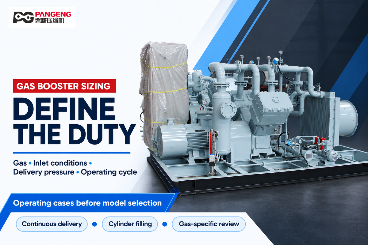
A booster is a gas compressor that increases the pressure of an existing gas supply. Its required size depends on the amount of gas the process needs and the conditions under which gas enters and leaves the package. Typical applications involving continuous delivery and filling require different capacity checks.
A booster normally receives compressed air or gas rather than starting from atmospheric suction. Industrial gases such as nitrogen, hydrogen and helium require their own gas composition and equipment assessment. A high-pressure air booster can’t be assigned to a different gas, solely because its pressure rating looks adequate.
For a scenario using common industrial piping, consider a stable central header with a long branch feeding the booster. The branch pressure during a simultaneous production draw is the relevant inlet condition. Quiet header conditions can mask pressure loss across the filter and regulator.
Define the discharge boundary just as carefully. If the process requires the specified pressure downstream of an after-cooler and distribution line, the package must cover these losses at the required flow. For nitrogen purity, generator capacity and storage-system inputs, use the separate nitrogen compressor sizing guide; the calculations below concentrate on the booster itself.
Put pressure and flow on one consistent basis
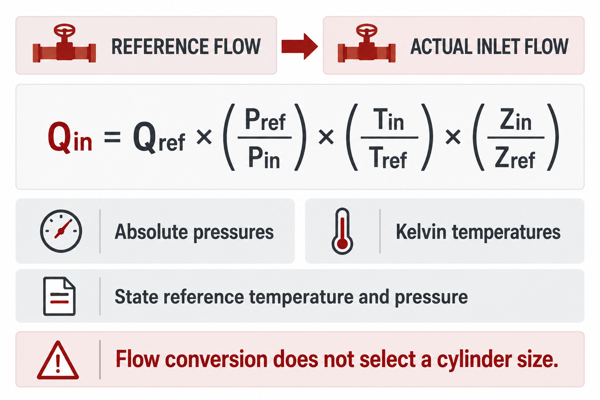
Convert gauge pressure to absolute pressure to find a compression ratio. Give temperature and pressure with all reference flow values. A normal cubic meter defines a quantity of gas at a stated reference condition. The inlet volume occupied by that gas varies with suction pressure, temperature and compressibility.
Which pressure belongs in the ratio?
Use absolute pressures for compressor inlet and outlet, including at low pressure. Gauge pressure reflects pressure above the local atmosphere. Absolute pressure includes the local atmosphere. The rule is the same, regardless of the unit (bar, MPa, psi, etc.) used by the measuring instrument.
Pabsolute = Pgauge + Patmospheric
Compression ratio = Pdischarge, absolute ÷ Psuction, absolute
Ariel’s reciprocating-compressor design explanation uses this absolute-pressure approach. Use the site’s atmospheric pressure for a real calculation; the worked example assumes 1.01325 bar, rather than treating that value as correct at every elevation.
How do you convert reference flow to inlet volume?
For the same gas composition and molar throughput, derive the conversion using the gas equation of state and conservation of gas quantity.
Qinlet = Qreference × (Preference / Pinlet) × (Tinlet / Treference) × (Zinlet / Zreference)
Use absolute pressures and Kelvin temperatures. Z is the compressibility factor for the gas at the given condition. This conversion gives the actual inlet flow rate; it doesn’t select a cylinder size.
NIST’s gas-flow standards determine gas quantity using pressure, temperature, volume and an equation of state. Write the reference temperature and pressure with Nm³/h, SCFM, or other reference flow value.
When comparing capacity between suppliers, convert SCFM or Actual CFM to the same stated reference basis before comparing. Otherwise, a higher-looking flow number can describe the same gas quantity at a different density. Verify if gas composition and flow basis are stated as wet or dry.
Work through a nitrogen booster sizing example
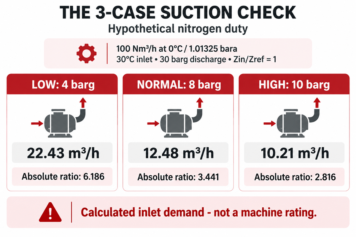
At 8 barg suction and 30°C, a hypothetical 100 Nm³/h duty requires 12.48 m³/h of actual inlet volume. This calculation converts gas demand; it doesn’t state a requirement for piston displacement or a machine rating. Repeating the calculation at lower and higher suction reveals the range a proposed model must cover.
Imagine nitrogen is supplied to a continuous process. Define normal volume at 0°C and 1.01325 bara, inlet temperature at 303.15 K, and discharge pressure at 30 barg. Set Zinlet/Zreference to 1 solely for this teaching calculation. A project calculation must use appropriate gas properties, especially as pressure rises.
The normal inlet pressure is 8 + 1.01325 = 9.01325 bara. Substitution gives 100 × (1.01325 ÷ 9.01325) × (303.15 ÷ 273.15) × 1 = 12.48 m³/h. The pressure ratio is (30 + 1.01325) ÷ 9.01325 = 3.441.
The 3-Case Suction Check
Use minimum, normal, and maximum suction rather than a single nominal point. This calculated table also shows how the inlet-volume demand changes if the required reference throughput is halved or increased by half. All rows have the same basic assumptions of ideal gas, discharge pressure and temperature.
| Suction case | Required flow Nm³/h |
Actual inlet flow m³/h |
Absolute ratio |
|---|---|---|---|
| Low: 4 barg | 50 | 11.22 | 6.186 |
| Low: 4 barg | 100 | 22.43 | 6.186 |
| Low: 4 barg | 150 | 33.65 | 6.186 |
| Normal: 8 barg | 50 | 6.24 | 3.441 |
| Normal: 8 barg | 100 | 12.48 | 3.441 |
| Normal: 8 barg | 150 | 18.71 | 3.441 |
| High: 10 barg | 50 | 5.11 | 2.816 |
| High: 10 barg | 100 | 10.21 | 2.816 |
| High: 10 barg | 150 | 15.32 | 2.816 |
A lower suction pressure results in less gas mass admitted per stroke for a given swept volume. The demanded inlet volume therefore increases for the same reference throughput. In a reciprocating compressor, this is also coupled with other factors like leakage. Clearance and valve behavior also affect volumetric efficiency. To account for these, the geometric displacement of the compressor must be greater than the inlet volume capacity by an appropriate model-specific allowance. This is why converting gas demand is just the starting point for the mechanical engineering selection.
Minimum suction can govern ratio and capacity, and a different point governs load. Ariel’s capacity-control guidance states that suction throttling can reduce power, affect discharge temperature and rod loads. A proposal made only at the normal inlet condition leaves the other cases unresolved.
Match the performance curve to the drive and duty
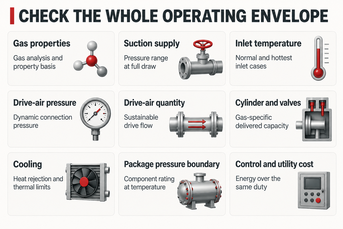
Select a booster from delivered capacity at the required gas, suction pressure, discharge pressure and drive conditions. The curve must cover the operating range, including continuous operation or the intended cycle. A maximum pressure, swept volume or motor rating alone can’t dictate how much gas the package will deliver.
For air-driven gas boosters, the drive-air supply is separate from the process-gas supply. For the cases described, the pressure available at the drive connection and the sustained air consumption both need to be evaluated. Choosing an air supply from its static pressure alone ignores the pressure drop that happens while the booster cycles.
- Confirm the curve basis: Match gas, temperature, flow reference and the exact model or configuration.
- Locate inlet and outlet conditions: Follow the correct inlet-pressure curve to the required delivery pressure.
- Read delivered flow and utility demand together: Check drive-air flow or package input power at that point.
- Check the remaining limits: Include temperature, gas compatibility, component pressure ratings, cooling and allowed operating cycle.
The HII gas-booster manual PDF describes its curves as estimates and ties air-consumption lines to specified drive conditions. Its two-stage notes also describe an interstage stall situation associated with inlet pressure and available drive force. That model-specific behavior is a reason to check the complete operating envelope, not a reason to extrapolate operating performance from a generic source.
A pneumatic booster at outlet stall has no useful sustained delivery. As downstream gas is consumed it may resume cycling; however, pressure and flow will depend on the conditions of the system and booster. Stall behavior doesn’t replace the package’s required overpressure protection.
Where a correct-looking selection can run out of capacity
| Constraint | What changes the result | Required check / owner |
|---|---|---|
| Gas properties | Molecular properties and compressibility differ | Gas analysis and valid property basis / process engineer |
| Suction supply | Source depletion or shared demand lowers inlet pressure | Pressure range at full draw / utilities team |
| Inlet temperature | Density and thermal load change | Normal and hottest inlet cases, plus ambient conditions / process engineer |
| Drive-air pressure | Pressure falls under drive flow | Dynamic pressure at the drive connection / utilities team |
| Drive-air quantity | The upstream air compressor cannot sustain consumption | Available air flow at required pressure / utilities team |
| Cylinder and valves | Displacement does not equal delivered capacity | Gas-specific performance and operating limits / manufacturer |
| Cooling | Hot gas or inadequate coolant restricts the duty | Heat rejection and thermal limits / plant engineer |
| Package pressure boundary | A valve, aftercooler or vessel can limit the assembly | Lowest applicable component rating at temperature / quality team |
| Control and utility cost | Recycle or unloaded operation consumes energy | Delivered flow and input energy over the duty / operations and finance |
Compression-ratio analysis looks at how discharge temperature and power are affected by the ratio. Limitations are usually specific to the manufacturer. Multi-stage compression and intercooling may be necessary. However, a fixed overall ratio doesn’t dictate a specific stage count. For hydrogen, gas-specific valve behavior also adds another reason to not transfer a nitrogen curve.
Air-driven, hydraulic and electric compressor types can each be adapted to perform specific functions. Consider the specified operating point, cycle life and utility burden before selecting a compressor based on drive type. Gas compression creates heat during the compression process with any drive type; gas-contact materials, cleanliness and site suitability need review, especially with oxygen supply or combustible gases.
Separate continuous supply from cylinder filling
Continuous service requires a steady state condition, where the delivered flow meets demand at the operating pressure. Filling a storage tank means adding a defined gas inventory, and changing the source and receiving pressures. Estimate the time required to make the fill by considering the flow available through successive receiving-pressure intervals and an explicit gas-temperature path. Consider the condition of the gas at delivery and final state.
For a constant-volume receiver, express the gas inventory on the same reference basis as the delivery curve:
Vreference = Vreceiver × (P / Preference) × (Treference / T) × (Zreference / Z)
Interval time = increase in reference inventory ÷ interval-average delivered reference flow
Find the inventory at each boundary, subtract the previous value, and then add the calculated interval times. For withdrawals, use a net accumulation rate. Falling source pressure means that average delivery must be determined using curve points matched to the changing source pressure.
A changing-flow example
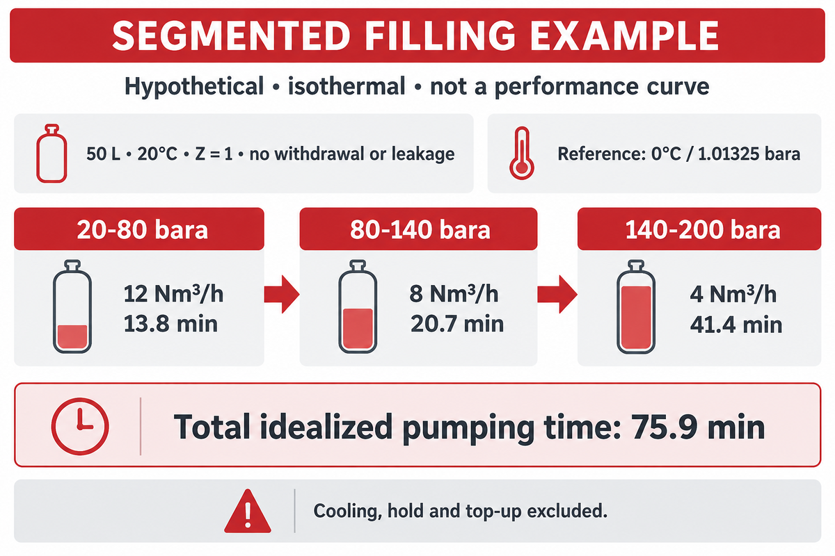
Consider a 50 L receiver at a constant 20°C (Z = 1), with no withdrawals and no leakage. Use the earlier 0°C/1.01325 bara reference basis. Consider three equal 60 bar increments between 20 and 200 bara, and assume interval-average delivery rates of 12, 8 and 4 Nm³/h. These rates are illustrative, and don’t represent an actual performance curve.
Each of those increments adds 0.050 (60/1.01325) (273.15/293.15) = 2.759 Nm³. Dividing that by each of the assumed flow rates gives the following idealized pumping times.
| Receiver interval | Assumed average delivery | Calculated time |
|---|---|---|
| 20–80 bara | 12 Nm³/h | 13.8 min |
| 80–140 bara | 8 Nm³/h | 20.7 min |
| 140–200 bara | 4 Nm³/h | 41.4 min |
The total time is about 75.9 minutes. Applying the initial 12 Nm³/h to the entire inventory would give about 41.4 minutes and miss the slower final part of this assumed curve. Smaller intervals improve the numerical approximation only when the flow and state inputs are themselves appropriate.
Filling thermodynamics matters. Real filling heats the gas, and the cylinder wall can be at a different temperature from the gas inside it. An OIML Bulletin study of industrial cylinder filling treats the uncertainties of pressure, temperature and compressibility together. The isothermal example given above, therefore, isolates the change of flow; it doesn’t predict the duration of a real fill.
Specify if the target is hot shutoff pressure or the gas quantity available after cooling. Idealized pumping time in the example excludes cooling, hold and controlled top up time. In compressed-air service, a receiver can buffer an intermittent draw and refill between events. However, it can’t create missing sustained gas production. See the DOE compressed-air storage guidance for that principle; process-gas vessel, materials, relief and installation requirements need gas-specific review.
Understand the cost consequences of sizing choices
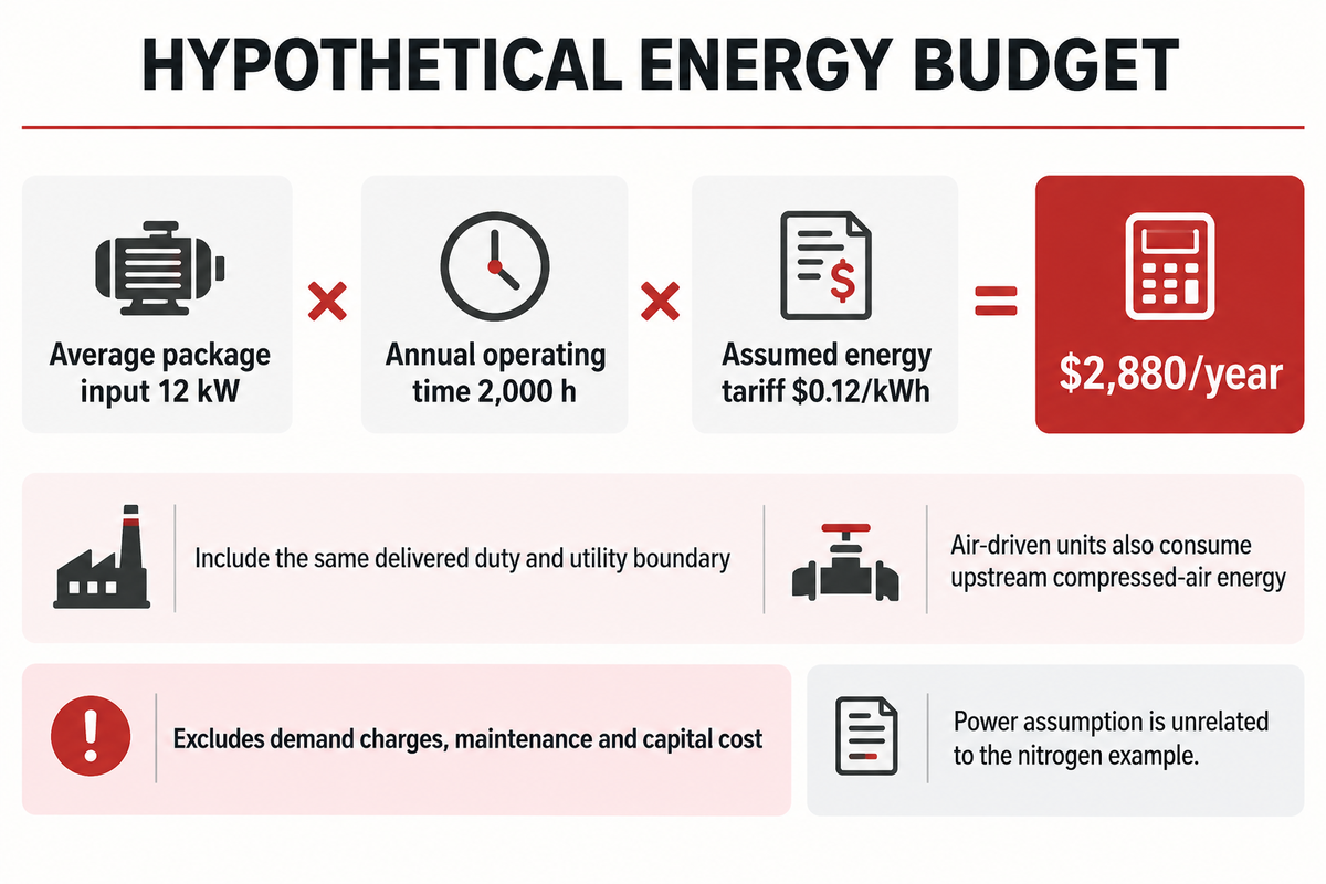
Compare energy consumption at the same delivered gas duty and measurement boundary. The average package electrical input, operating hours and tariff give the energy charge for an electric unit. For a pneumatic unit, include upstream compressed-air production and conditioning burden. The booster body’s lack of an electric motor doesn’t make operation free.
“The total electrical power input to a compressor”
CAGI’s definition includes auxiliary drive and cooling loads. For billing calculations, use the average input over the actual operating cycle rather than use motor nameplate output. Natural Resources Canada’s compressed-air guide also shows why control mode changes part-load energy use.
For a hypothetical budget, let’s assume a measured average package input of 12 kW, 2,000 hours of operation per year, and an energy tariff of $0.12 per kWh. The energy charge would be 12 × 2,000 × 0.12 = $2,880 per year. This example doesn’t include demand charges, maintenance costs or capital costs. The assumed power isn’t related to the nitrogen sizing example.
The right compressor must meet the delivery requirement as well as the energy budget. Ask procurement to compare complete booster packages with the same included cooling, controls and gas-contact specification. Finance should compare utility use over the same duty schedule to judge which offer is energy-efficient in service. Application-specific design requirements can change purchase cost, so neither pressure alone nor a universal percentage predicts the quotation.
Turn the calculations into a supplier-ready duty sheet
Send the operating cases, and require a delivered-flow response for each. The useful supplier output is a performance selection based on gas, utility demand, and limiting conditions. A nominal model name, headline discharge pressure, or a general compressor sizing guide doesn’t satisfy those conditions.
For the worked nitrogen duty, the request for acceptance may read as follows: “Please confirm continuous delivered flow on the stated normal-volume basis at each suction condition mentioned, with the specified discharge pressure and inlet temperature. State the governing mechanical, thermal and drive limits and required utilities.” Include complete analysis of the gas and allowable variations when the gas source is changed.
A manufacturer should provide the applicable performance curves or selection output, a readable PDF file, package boundaries and the basis for its guarantee. Revisions should be tracked to the same duty cases to check that a revised offer hasn’t altered the temperature, flow reference or included auxiliaries.
For natural-gas duties, PanGeng’s existing natural-gas compressor size calculator can give an initial series and stage estimate. Use the result as a starting point for this natural-gas operating case check; nitrogen and other gases need their own gas-specific selection. For nitrogen equipment options, review the PanGeng nitrogen compressor range, and send the operating cases for a sizing check.
Frequently asked questions
Can a gas booster work with any primary compressor?
No. The upstream supply must meet the booster’s gas, pressure, flow and quality requirements. A unit intended for clean compressed air isn’t automatically suitable for another process gas. Check the available supply during peak demand, including drive-air demand where applicable. The primary machine’s nameplate capacity alone doesn’t establish the booster inlet condition.
What pressure can a gas booster achieve?
There’s no universal pressure ceiling for gas boosters. Achievable pressure depends on the model, inlet pressure, drive conditions, staging and package limits. Choose for the required pressure and flow together. A high-pressure compressor’s maximum rating or a pneumatic unit’s stall point doesn’t tell you the sustained delivery available at your operating point.
Can the same compressor handle different gases?
Some models can, subject to the manufacturer’s gas-specific approval and configuration. Gas properties affect density, temperature rise and valve behavior. Materials, seals, cleanliness and leakage requirements also matter. A nitrogen calculation can’t be copied unchanged for hydrogen, CO₂ or oxygen, even when the requested pressure and flow rate look identical.
Should sizing use normal or minimum inlet pressure?
Use minimum, normal and maximum inlet conditions. Minimum suction can govern capacity; another point can govern power or mechanical limits. The supplier must check the full range.
Is a booster more efficient than a separate high-pressure compressor?
It can be useful when a suitable pressurized gas supply already exists, but the energy efficiency comparison must include that supply. Compare both systems at the same delivered gas quantity, final pressure, operating schedule and utility boundary. Air-driven boosters also consume upstream air-compression energy. Control mode, cooling and part-load behavior can change the result, so a drive label alone can’t establish a winner.
Is a sizing calculator enough to order a booster?
A calculator can help organize inputs and preliminary options. Ordering still requires the selected configuration’s performance over the submitted operating cases, suitable gas-contact construction and available utilities. Confirm the manufacturer’s guaranteed delivery and stated limits before accepting the machine.
When is an oil-free compressor needed?
Use an oil-free compressor when the process specification requires the gas path to avoid lubricating-oil contamination. Specify the allowable contamination and measurement boundary rather than relying on the label alone. An oil-free gas section doesn’t remove particles, moisture or contaminants already present in the incoming gas, and it doesn’t establish oxygen-service suitability. Air quality, gas purity and material compatibility remain separate checks. In the quotation, identify the incoming-gas specification and the required condition at the package outlet. That makes the supplier responsible for a defined delivery boundary, rather than an undefined promise of clean gas.
Calculation scope: The numerical examples are hypothetical and use explicit ideal-gas or isothermal assumptions to explain the method. Final compressor selection needs gas-specific properties and manufacturer performance data. Cylinder-filling equipment and procedures require their own application review.
References & Sources
- NIST: gas-flow measurement and equation-of-state basis
- NIST: pressure and gas-flow unit conversions
- OIML Bulletin: metrological validation of industrial gas-cylinder filling, 2025
- CAGI: compressed-air technical resource library and glossary
- Natural Resources Canada: compressed-air energy reference guide
- U.S. DOE: compressed-air storage, Tip Sheet 9
- Pumps & Systems: why compression ratio matters
- Pumps & Systems: compressor selection and sizing considerations
- Compressortech2: valve behavior in hydrogen compression