Get in Touch with Pangeng

Electrochemical Hydrogen Compressor Engineering Integration Guide

Contents
show
An electrochemical hydrogen compressor is a device that moves hydrogen through an ion-conducting membrane and raises pressure without a mechanical piston in the gas path. A usable project specification still needs more than a pressure target: it must bind feed composition, membrane chemistry, thermal and water balance, structural support, controls, facility safety, and acceptance evidence to one declared duty point.
Updated August 2026 · Informational engineering guide for hydrogen-system integrators and industrial buyers
TL;DR
Do not select or accept an EHC by maximum pressure alone. Freeze the five integration boundaries, test seven evidence stages under declared conditions, and route unresolved commercial configuration questions to the solution owner.
Project Inputs to Freeze Before Engineering Review
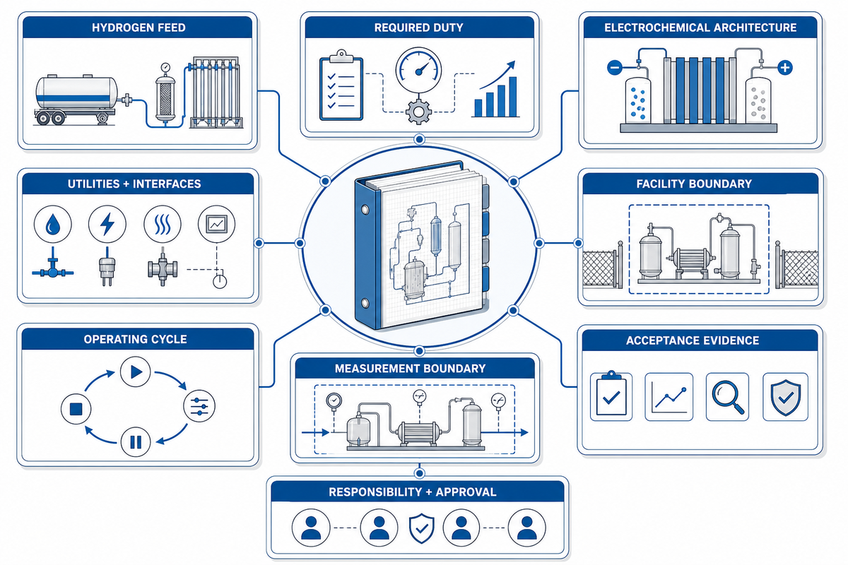
| Input | Record | Why it changes the evidence |
|---|---|---|
| Hydrogen feed | Composition, contaminants, inlet pressure, temperature, dew point | Membrane compatibility and purification claims are condition-dependent |
| Required duty | Inlet/outlet pressure, mass flow, turndown, operating pattern | Maximum pressure does not prove throughput or efficiency |
| Electrochemical architecture | Membrane chemistry, temperature regime, cell geometry, number of stages | PFSA and high-temperature PBI evidence cannot be interchanged |
| Utilities and interfaces | Power, cooling, water or humidification, purge gas, vent and drain paths | Balance-of-plant limits can dominate startup and stability |
| Facility boundary | Location, ventilation, hydrogen detection, electrical classification, authority review | Package readiness is not installation approval |
| Acceptance evidence | Test conditions, instruments, uncertainty, limits, deviations, retained records | Makes a result reproducible and contractually reviewable |
| Operating cycle | Starts, ramps, steady periods, standby and shutdowns | Control and durability evidence must match the real cycle |
| Measurement boundary | Hydrogen throughput, electrical input and auxiliary loads | Prevents mismatched efficiency numerators and denominators |
| Responsibility and approval | Supplier, EPC, site and authority roles | Keeps acceptance gaps from becoming unowned assumptions |
What Electrochemical Hydrogen Compression Does at the Cell Boundary
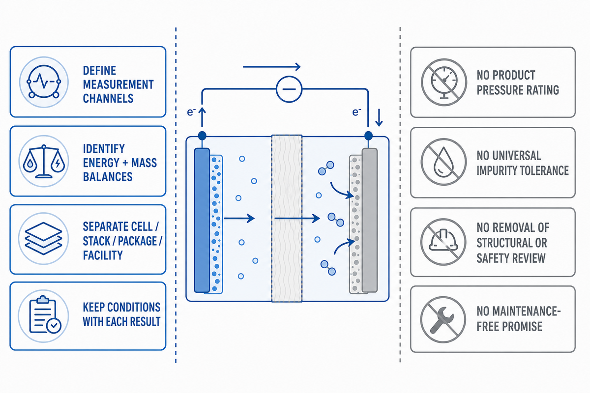
At the anode, hydrogen molecules are oxidized into protons and electrons. The protons cross an ion-conducting membrane, while electrons travel through an external circuit; hydrogen then reforms at the cathode on the higher-pressure side. The U.S. Department of Energy overview describes this proton-exchange-membrane mechanism, and a 2025 analytical review covers the same operating principles and component boundaries.
This operating principle is electrochemical compression: a PEM or another qualified ion-conducting architecture uses electrical work to compress hydrogen. Compared with mechanical compressors, electrochemical hydrogen compression removes a reciprocating piston from the gas path, but it doesn’t remove the need to define a complete compression system.
In electrochemical hydrogen compression technology, a qualified polymer electrolyte moves protons through the membrane to the cathode, where they recombine as hydrogen; unlike a proton exchange membrane fuel cell, the compressor does not use hydrogen and oxygen to produce electricity.
That cell-level explanation is useful but incomplete for engineering. Pressure develops because the electrochemical reaction transports hydrogen against a pressure gradient, and the electrical input, membrane resistance, mass transport, gas crossover, water transport, heat, seals, structural support, and downstream backpressure all affect the observed result. The electrochemical hydrogen compressor working principle explains transport, but it doesn’t establish a transferable package duty point.
Use the mechanism to
- Define measurement channels
- Identify energy and mass balances
- Separate cell, stack, package, and facility evidence
- Explain why conditions travel with every result
Do not use it to
- Infer a product pressure rating
- Claim universal impurity tolerance
- Remove structural or safety review
- Promise maintenance-free operation
“No moving parts in the gas path” doesn’t mean “no degradation” or “no balance of plant.” The membrane-electrode assembly, gas-diffusion layers, seals, end plates, manifolds, sensors, power electronics, valves, relief devices, cooling, vents, and detection system still create maintenance and evidence obligations.
Build the EHC Integration Boundary Ledger Before Sizing
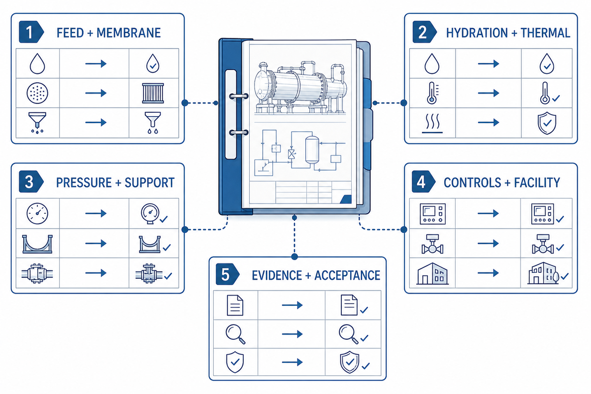
The EHC Integration Boundary Ledger is an editorial project-definition method with five entries: Feed and Membrane Compatibility; Hydration and Thermal Regime; Pressure and Structural Support; Controls and Facility Safety; Evidence and Acceptance. It isn’t an industry standard, certification, patented PanGeng method, or substitute for a hazard review.
| Boundary | Minimum project questions | Evidence to retain | Failure if omitted |
|---|---|---|---|
| 1. Feed and membrane | Which membrane, feed species, contaminant range, inlet state? | Feed analysis, compatibility basis, outlet-quality method | Purity or durability inferred beyond tested conditions |
| 2. Hydration and thermal | PFSA or PBI, humidified or non-humidified, what heat balance? | Temperature, humidity or dew point, condensate and cooling record | Dry-out, flooding, resistance rise, or false regime transfer |
| 3. Pressure and support | What flow, differential pressure, geometry, staging, and support? | Condition-matched performance plus structural method | Pressure headline detached from deformation or throughput |
| 4. Controls and facility | Which trips, isolation states, vents, detection, and local rules? | Cause-and-effect matrix and facility interface review | Package starts while the installation remains unsafe |
| 5. Evidence and acceptance | What is measured, by whom, with what limit and uncertainty? | Approved procedure, calibration chain, deviations, signatures | A startup observation is mistaken for accepted performance |
Start sizing only after the map has owners. For example, the supplier may own package performance evidence, the engineering contractor may own utility and relief interfaces, the site may own operating conditions, and the local authority may own approval decisions. Responsibility left implied is not a closed boundary.
The duty point should state inlet and outlet pressure, target mass flow, feed composition, temperature and humidity regime, operating duration, turndown, restart pattern, and allowed product-quality window. If one of those changes, the evidence-transfer decision must be revisited.
Set Feed-Gas Purity and Contamination Boundaries
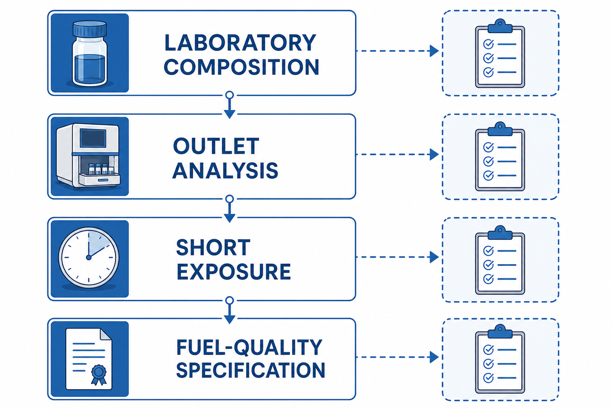
An EHC can combine compression with selective hydrogen transport, but “purifies hydrogen” isn’t a complete specification. Defensible evidence names the membrane chemistry, feed species and concentration, pressure and temperature, current density, humidity regime, test duration, outlet sampling method, detection limits, and any performance loss during exposure.
Separate three questions: can the species cross the membrane, can it poison or alter the catalyst and membrane, and can it accumulate or react elsewhere in the package? A low outlet reading doesn’t by itself prove long-term tolerance, and an impurity-tolerance result under one reformate mixture doesn’t authorize a different feed.
| Feed evidence | Question it answers | Question it does not answer |
|---|---|---|
| Laboratory composition | What entered during the reported test? | Whether site excursions stay inside that composition |
| Outlet analysis | What the stated method detected at the outlet? | Universal fuel quality or long-term catalyst health |
| Short exposure | Immediate performance response | Recovery, cumulative damage, or service interval |
| Fuel-quality specification | Required product characteristics within its scope | Whether this compressor produces them from this feed |
ISO 14687:2025 specifies minimum hydrogen-fuel quality characteristics across stated applications. Use the current edition and applicable destination requirements to define the product target, then prove the actual inlet-to-outlet result; the standard catalogue page does not certify an unnamed compressor.
Feed transients deserve their own record. Startups, upstream regeneration, electrolyzer changes, purge transitions, and analyzer lag can create exposure outside a steady-state sample. Define what the control system does when composition is unknown or outside the agreed envelope.
Where electrolysis is producing hydrogen upstream, state how hydrogen is supplied during ramp, standby and restart. That interface can change inlet pressure, moisture and contaminant exposure even when the nominal hydrogen production rate looks stable.
Whether the inlet comes from electrolysis for hydrogen, a green hydrogen project, or another hydrogen generation train powered by renewable energy such as wind and solar, retain the actual feed data rather than inferring quality from the upstream label.
Manage Water Without Treating Hydration as a Fixed Setpoint
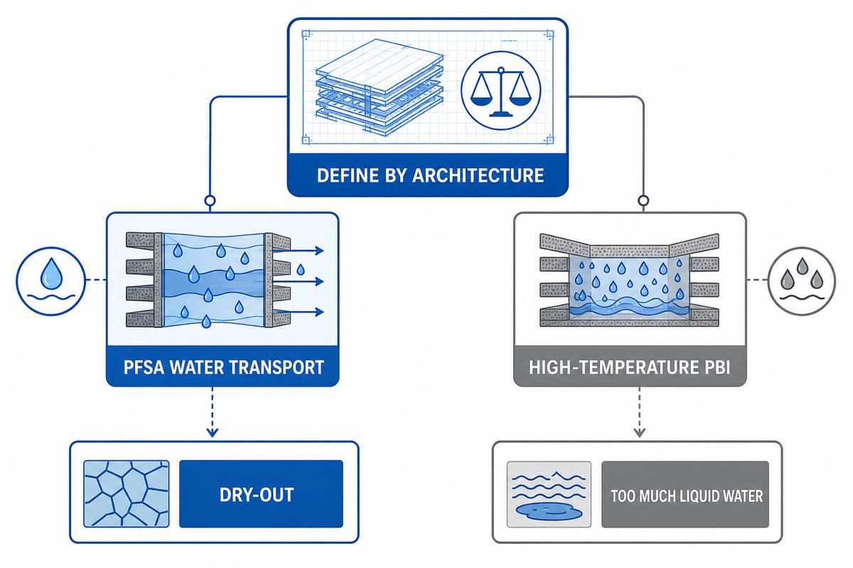
For low-temperature PFSA systems, water transport is coupled to temperature, current density, pressure, gas flow, membrane thickness, electro-osmotic drag, and back diffusion. A peer-reviewed water-transport study reported an anode relative-humidity decline from 90% to 55% under one stated 32 bar, 60 °C and 0.66 A/cm² condition. That’s evidence of sensitivity, not a universal setpoint.
Dry-out can raise membrane resistance and destabilize performance; too much liquid water can obstruct transport, alter differential pressure, or upset downstream handling. Because both failure directions are possible, a single inlet-humidity number isn’t enough. Record inlet and outlet moisture, cell or stack temperature, current, voltage, pressure, flow, condensate behavior, and the timing of each signal.
Architecture counterexample
High-temperature phosphoric-acid-doped PBI research has demonstrated hydrogen pumping above 100 °C under non-humidified and humidified conditions, including specified reformate feeds. That evidence prevents a PFSA hydration rule from being presented as technology-neutral, but it doesn’t establish a high-pressure package rating.
Define the water balance by architecture. PFSA review may need humidifier performance, dew point, condensate separation, freeze protection, and water carryover. PBI review may instead focus on acid inventory, operating temperature, feed effects, thermal transitions, and the evidence behind non-humidified operation.
Don’t tune hydration by chasing one voltage or pressure value. Change one approved variable at a time, keep the inlet condition stable long enough for the system response to develop, and retain the full trend. If the result can’t be reproduced under the same declared conditions, it isn’t a dependable acceptance point.
Validate Pressure Ratio, Flow, Crossover, and Structural Support Together
Pressure evidence becomes useful only when paired with hydrogen throughput, electrical input, current density, cell count, temperature, inlet condition, differential pressure, crossover method, stability duration, and uncertainty. One 2025 three-cell serial-stack study reported more than 120 bar, yet its reported efficiency changed from above 64% below 0.03 kg/day to 12% above 0.17 kg/day. The point isn’t to copy those values; it’s to keep flow attached to every pressure and efficiency claim.
Staging changes more than the pressure ratio. It can change intermediate cooling or water handling, electrical arrangement, control transitions, leakage paths, seals, measurement locations, and failure propagation. The required evidence must follow each stage rather than treating the stack as one black box.
For hydrogen compression and storage duty, report output pressure with flow, hydrogen crossover, and the hydrogen storage boundary so the compression of hydrogen is not separated from the material balance.
Pressure is also a mechanical boundary. A 2024 tubular EHC study challenged the assumption that planar geometry transfers cleanly to high differential pressure, while a separate mechanical study found that gas-diffusion-layer thickness and flow-field geometry affect deformation and stress. Include membrane support, diffusion media, end plates, sealing, manifolds, and the structural-analysis or test basis in the review.
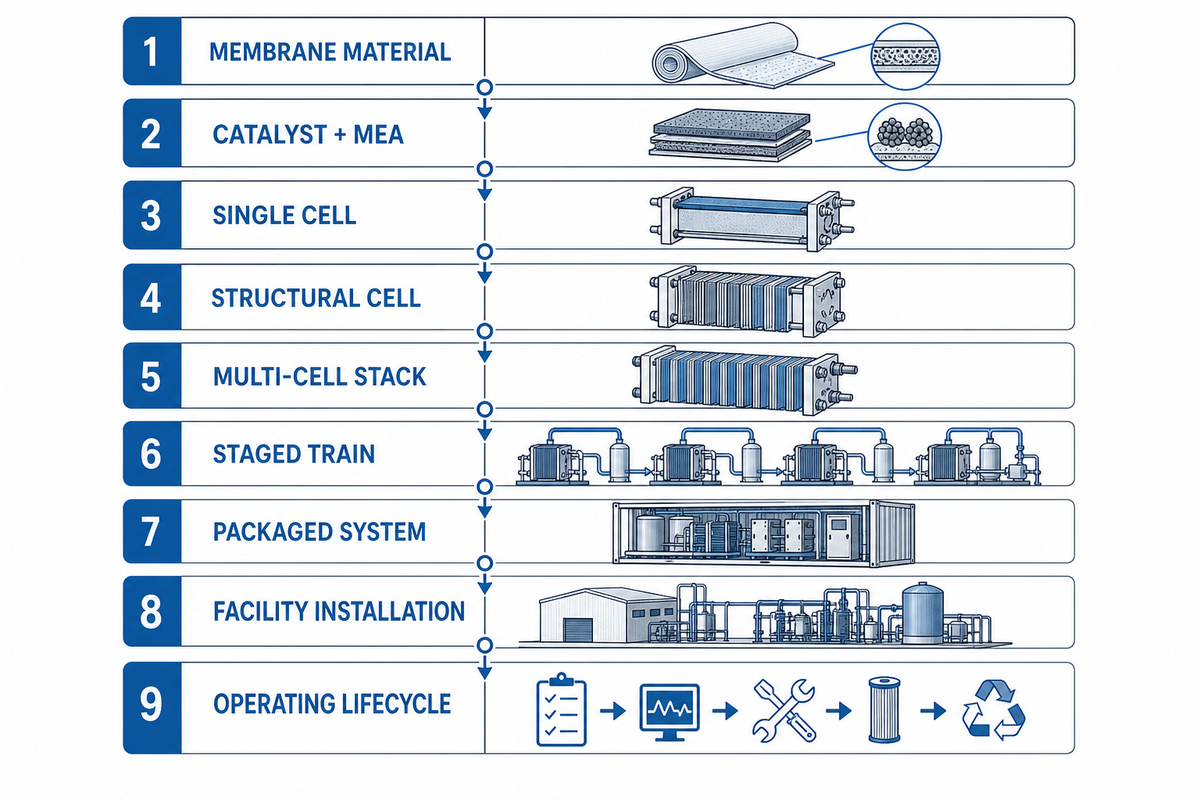
| Evidence tier | Evidence | Transfer limit |
|---|---|---|
| 1. Membrane material | Transport, permeability, chemistry and thermal regime | Does not prove catalyst, assembly strength or seals |
| 2. Catalyst and MEA | Reaction, feed exposure, resistance and recovery behavior | Does not prove supported cell geometry |
| 3. Single cell | Flow, current, voltage, crossover, temperature and pressure | Does not prove repeatability across cells |
| 4. Structural cell | GDL, flow field, end plate, seal, deformation and stress basis | Does not prove manifold or stack balance |
| 5. Multi-cell stack | Cell dispersion, manifold balance, stability and shared thermal state | Does not prove stage transitions |
| 6. Staged train | Intermediate pressure, cooling, water handling, isolation and controls | Does not prove auxiliary-system capacity |
| 7. Packaged system | Power, cooling, separation, isolation, relief and leak integrity | Does not prove site interfaces |
| 8. Facility installation | Ventilation, detection, vent destination, electrical and emergency interfaces | Depends on jurisdiction and actual layout |
| 9. Operating lifecycle | Starts, stops, feed excursions, drift, maintenance and retained trends | Requires time-matched site evidence |
Define stop conditions before pressure is introduced. They may include leak, pressure, temperature, voltage dispersion, current, water imbalance, gas-quality, ventilation, or detection events, but their values must come from the approved design and hazard analysis. This guide deliberately supplies no universal trip values.
Define the Minimum Instrumentation and Interlock Matrix
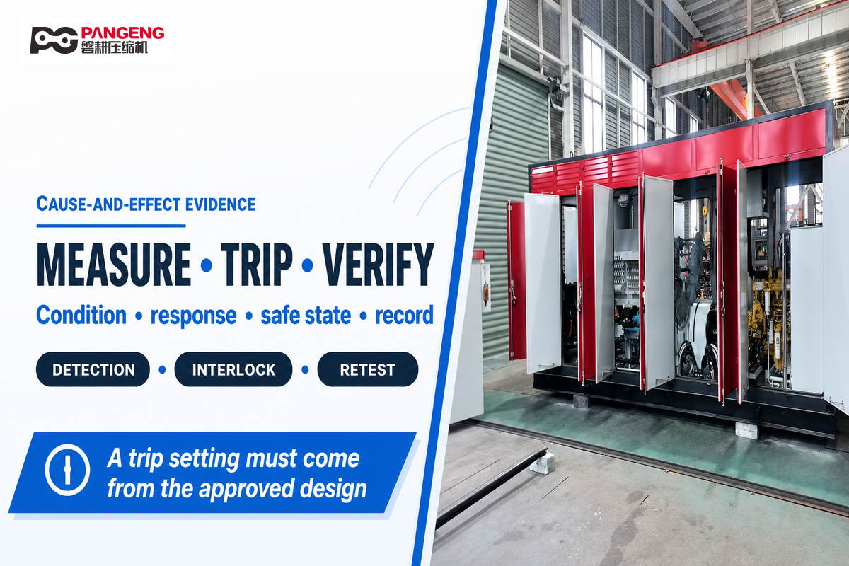
Instrumentation should enable the team to differentiate process change from sensor fault and package fault from facility condition. At a minimum, pressure, flow, temperature, humidity or dew point where relevant, cell or stack voltage, current, power, product quality, hydrogen detection, ventilation status, valve position, relief or vent status and emergency shutdown feedback should be time-synchronized.
A 2025 peer-reviewed EHP researcher guide hosted in the Helmholtz-Zentrum Berlin repository includes humidity, temperature, mass flow, pressure and electrochemical channels, user-defined software limits, hardware protection, relief devices and hydrogen-leak response. It supports a measurement architecture, not universal alarm values. NIST’s Transient Flow Facility separately shows why fast, calibrated, synchronized measurements matter when gas conditions change rapidly.
The NIST facility reports pressure and temperature channels with time resolution of 100 ms or less across a 0–10 kg/min flow range and pressures up to 70 MPa. Those metrology capabilities aren’t EHC requirements; they demonstrate why sensor range, response time and synchronization must be specified when analyzing transient results.
| Initiator | Detection | Automatic action | Required feedback | Restart authority |
|---|---|---|---|---|
| Hydrogen detection event | Named detector and health state | Project-defined isolation, shutdown and ventilation response | Valve, power, alarm and ventilation confirmation | Named responsible role after cause closure |
| Pressure deviation | Independent or validated pressure channel | Controlled current reduction, isolation or shutdown | Safe pressure and valve-state evidence | Approved operating procedure |
| Thermal or hydration deviation | Architecture-specific sensors and plausibility checks | Project-defined load reduction or safe stop | Trend stability and water-path status | Technical review if limits were exceeded |
| Instrument fault | Range, rate, redundancy or heartbeat logic | Fallback state defined by the hazard analysis | Fault identity and safe-state confirmation | Instrument repair and function test |
Facility controls can’t be reduced to package interlocks. OSHA 29 CFR 1910.103 addresses hydrogen-service accessories, ventilation, electrical equipment and gas-tight testing within its U.S. scope. DOE also emphasizes ventilation, leak detection and special flame detection; however, the relevant code, engineering design and local authority requirements govern the actual installation.
Hydrogen refueling stations are one type of hydrogen infrastructure; broader labels such as clean hydrogen or the hydrogen economy do not alter the project-specific control and code evidence.
Record instrument identity, range, accuracy or uncertainty, calibration status, location and response time. NIST calibration policy warns that calibration alone does not establish metrological traceability: the unbroken comparison chain and measurement uncertainty matter, as do method, operator and environmental conditions.
Run the Seven-Test EHC Acceptance Evidence Matrix
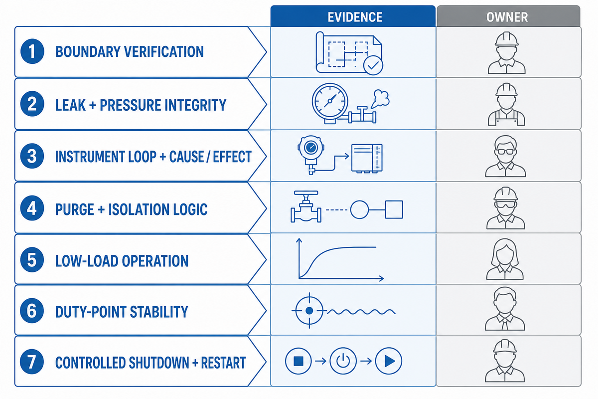
The EHC Acceptance Evidence Matrix is an editorial engineering template organized as seven project tests. It is not a universal EHC acceptance standard, and its sequence does not replace the approved project procedure, manufacturer instructions, hazard analysis, or local authority requirements.
“A standardized procedure to evaluate the performance of EHPs is lacking.”
2025 peer-reviewed EHP researcher guide hosted in the Helmholtz-Zentrum Berlin repository
The Helmholtz guide proposes an initial six-step laboratory benchmarking approach—purge, warm-up, pressurization, break-in, performance characterization and diagnostics—and explicitly limits its universality. The seven tests below translate that insight into a project evidence package by separating instrument loops and controlled shutdown/restart; they do not claim standards ownership.
| Test | Purpose | Record | Pass/fail owner |
|---|---|---|---|
| 1. Boundary verification | Confirm configuration, utilities, feed, vents, documents and authority holds | As-built identity, revision, open items, signed readiness | Project responsibility matrix |
| 2. Leak and pressure integrity | Verify the approved pressure boundary before hydrogen operation | Medium, pressure, time, temperature, method, instruments, deviations | Approved design/test procedure |
| 3. Instrument-loop and cause/effect | Prove channels, alarms, safe states and feedback | Injected condition, response, timing, final state, exceptions | Approved cause-and-effect matrix |
| 4. Purge and isolation logic | Verify defined sequences without assuming universal duration | Valve states, gas analysis, timing, interlocks, vent destination | Project procedure and hazard review |
| 5. Low-load operation | Confirm stable thermal, hydration, electrical and gas response | Synchronized baseline trends and hold criteria | Supplier and project-approved limits |
| 6. Duty-point stability | Demonstrate flow, pressure, quality and electrical performance together | Declared conditions, uncertainty, duration, dispersion, excursions | Contract acceptance basis |
| 7. Controlled shutdown and restart | Verify safe transition, retained state and authorized recovery | Pressure decay, isolation, purge, alarms, restart prerequisites | Operating and emergency procedures |
For hydrogen fuelling stations, ISO 19880-1:2020 includes compression within broader design, installation, commissioning, operation, inspection and maintenance requirements. Its scope and design-specific precautions do not make this seven-test pack an ISO-derived EHC procedure.
Close each test with status, deviation, corrective action, retest, responsible reviewer, record location and unresolved risk. “Started successfully” is an observation; acceptance needs an agreed criterion and traceable evidence.
Diagnose Pressure, Purity, and Efficiency Shortfalls by Measurement
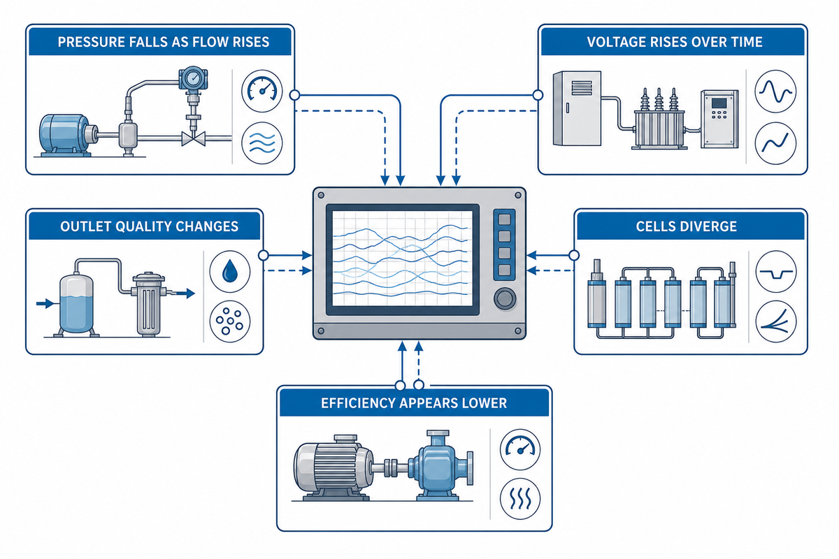
Follow the time sequence and location of measurement. If discharge pressure is low, the cause could be feed restriction, inadequate current, membrane resistance, water imbalance, crossover, external leakage, valve status, backpressure behaviour, structural change, sensor fault or a load point outside the demonstrated envelope.
| Observed pattern | Correlate first | Possible boundary | Do not conclude yet |
|---|---|---|---|
| Pressure falls as flow rises | Inlet pressure, mass flow, current, voltage, temperature, backpressure | Duty mismatch, transport loss, feed restriction or control limit | That the membrane alone failed |
| Voltage rises over time | Humidity or dew point, temperature, current, cell dispersion | Hydration drift, resistance, contact or thermal change | One universal dry-out diagnosis |
| Outlet quality changes | Feed sample, analyzer status, pressure, flow, crossover and event timing | Feed excursion, transport, leak path or measurement lag | Permanent loss of selectivity |
| Cells diverge | Individual voltage, temperature, flow/manifold state and pressure | Distribution, local resistance, water or instrumentation | That the entire stack is equivalent |
| Efficiency appears lower | Electrical boundary, hydrogen throughput, inlet/outlet state and test method | Real degradation, changed duty, auxiliary load or calculation basis | A like-for-like loss before normalization |
Compare a suspect event to a known-good record at matched conditions. If temperature, feed, humidity, current density, flow, pressure ratio, instrument range, or auxiliary load boundary changed, normalize or repeat before interpreting the outcome as degradation.
Stop invasive work when pressure, hydrogen, electrical or chemical hazards are unresolved. The diagnostic matrix organizes evidence for qualified personnel; it does not authorize bypassing interlocks, opening a pressurized assembly, changing setpoints, or restarting after a safety event.
For maintenance planning after commissioning, use the hydrogen compressor maintenance guide to build a condition-based record. Keep EHC-specific membrane and electrochemical evidence attached rather than replacing it with a generic compressor interval.
How Recent Research Changes Integration Priorities
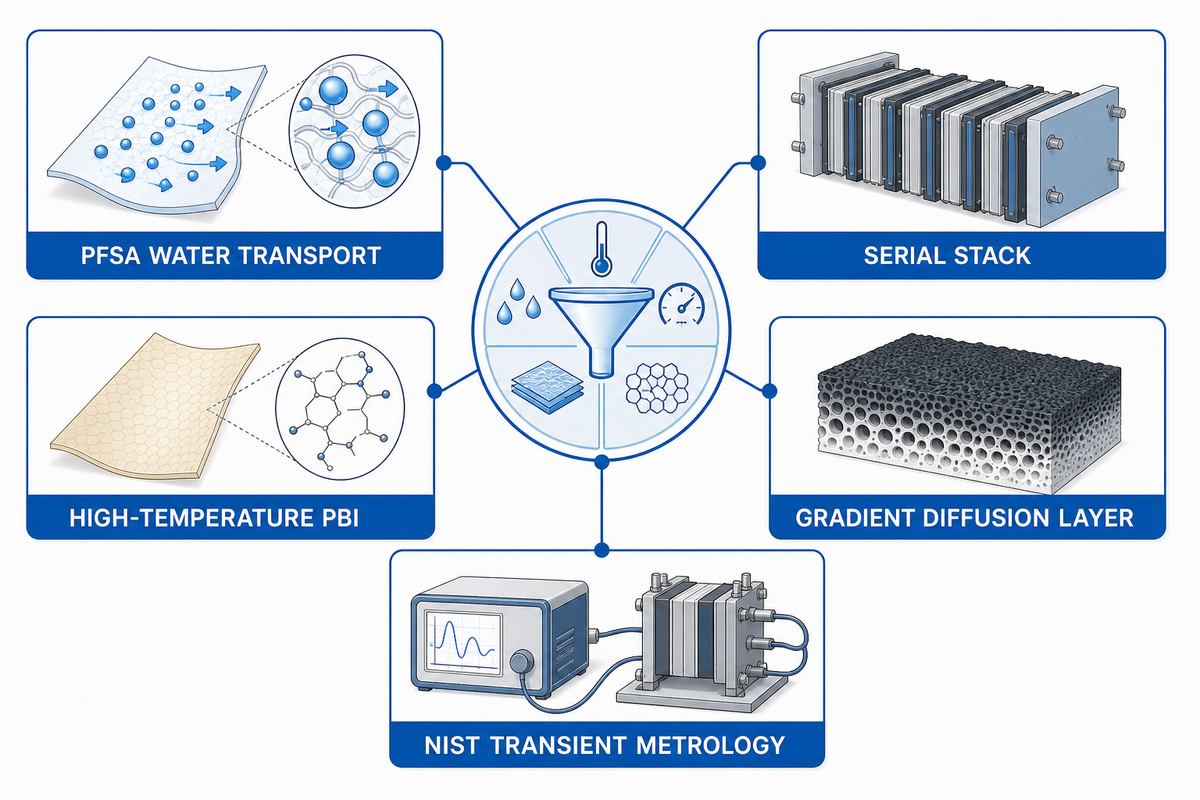
Recent work shifts the useful question from “what pressure has a cell reached?” to “under what membrane, flow, structural and control conditions can the result be transferred?” Water-management studies, serial-stack research, operating-parameter models, wettability-gradient diffusion layers, tubular geometry and mechanical deformation studies all point toward condition-rich evidence. A review of electrochemical hydrogen compressor recent progress and challenges is useful only when each result keeps those conditions attached.
One degradation study covered 30–90 °C, 30–90 kPa inlet pressure and a 1.0–2.0 hydrogen stoichiometric ratio, while a 2025 diffusion-layer study reported 1.0 MPa after 62 s at its stated 50% relative humidity and 0.3 V condition. These values belong to their experiments and serve as examples of how much context a number needs before transfer.
| Study focus | Reported condition or result | How to use it |
|---|---|---|
| PFSA water transport | 32 bar, 60 °C, 0.66 A/cm²; anode RH changed from 90% to 55% | Evidence that water balance is condition-sensitive, not a humidity target |
| Serial stack | Above 120 bar; above 64% efficiency below 0.03 kg/day and 12% above 0.17 kg/day | Keep throughput attached to pressure and efficiency |
| High-temperature PBI | Above 100 °C with testing approaching 4,000 h under reported feeds | Counterexample to PFSA-only hydration assumptions |
| Gradient diffusion layer | 1.0 MPa in 62 s at 50% RH and 0.3 V in the reported cell | Mechanism evidence, not a package duty point |
| NIST transient metrology | 100 ms or faster; 0–10 kg/min and up to 70 MPa facility ranges | Metrology context, not required EHC sensor ranges |
The change is practical. Buyers should ask for a test matrix around the intended duty, not a single best point; cell-to-cell dispersion, not only stack average; structural and crossover evidence at differential pressure, not only electrochemical polarization; and degradation or recovery after relevant feed and thermal events, not only a fresh-cell result.
Patent literature can reveal approaches to water management, serial electrical connection, membrane thickness and alternative electrochemical media. The reviewed patent records attribute specific claimed approaches to recorded assignees including Plug Power, Southern University of Science and Technology, Ergosup, and Textron/Bell, not PanGeng; the records also carry different legal statuses. Patent publication is not independent proof of commercial performance.
Research-to-project transfer rule
Transfer a result only when membrane chemistry, feed, temperature, hydration, pressure, flow, current density, geometry, support, measurement boundary and duration are sufficiently matched. Otherwise use it to design a test, not to promise a result.
Standards also move. ISO 14687:2025 and NFPA 2:2026 are current editions reviewed for this guide, while project applicability still depends on location, system type and the authority having jurisdiction. Record edition and access date so a commissioning package does not silently inherit a superseded reference.
Prepare an Engineering Handoff Without Duplicating the Solution Page
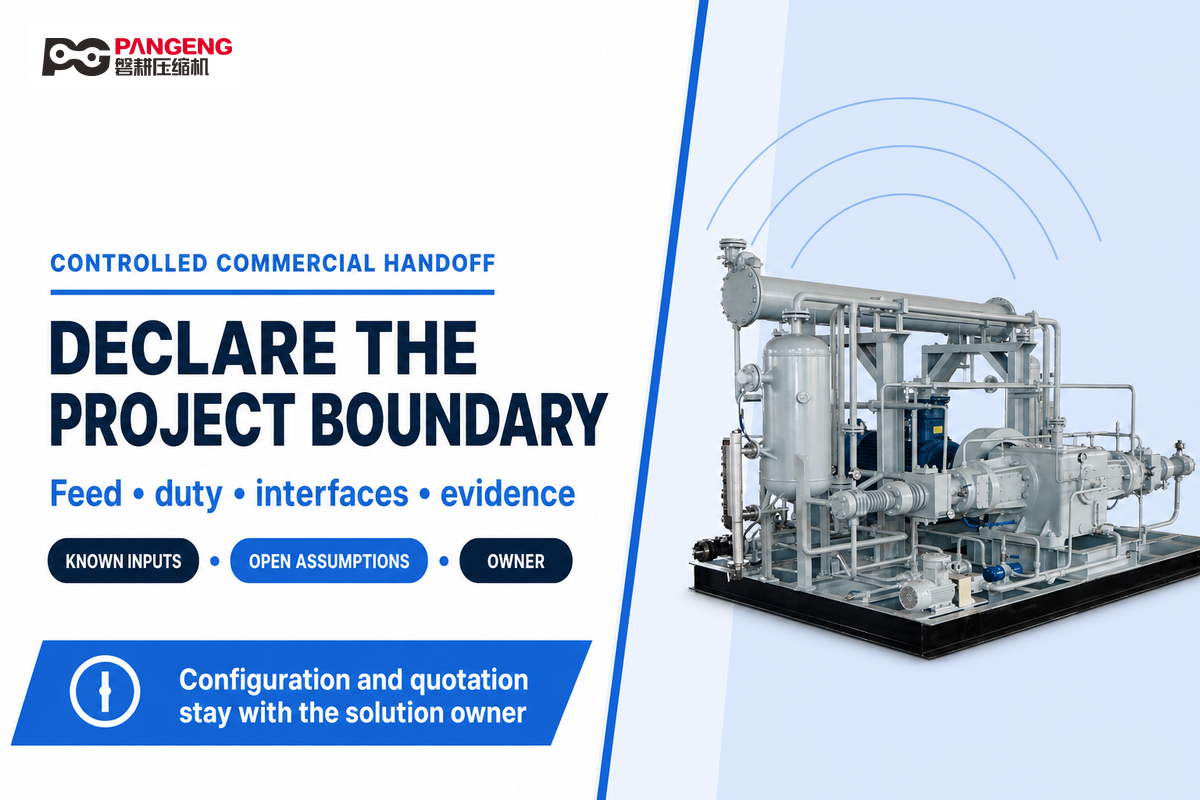
Good handoff evidence lets the supplier evaluate feasibility without asking the blog to act like a product catalogue. Copy the checklist below into the inquiry, mark every assumption, and identify who owns the missing data.
If the architecture remains open, compare metal hydride hydrogen compressors with electrochemical hydrogen compression operations explicitly, and ask whether a PFSA design actually uses Nafion before treating one membrane brand as the definition of hydrogen transported electrochemically.
RFQ checklist — copy these into your engineering request:
| Parameter | Recommended range | Why it matters | How to verify |
|---|---|---|---|
| Feed composition | Declared normal, startup and excursion envelope | Sets membrane and catalyst compatibility | Sampling plan and laboratory/analyzer method |
| Pressure and flow | Required inlet/outlet conditions across the duty cycle | Defines useful compression work | Condition-matched performance test |
| Thermal/water regime | Architecture-specific allowable envelope | Prevents PFSA/PBI rule transfer | Temperature, moisture and stability trends |
| Product quality | Application and destination-specific specification | Defines outlet acceptance | Named method, detection limit and sample point |
| Utilities/interfaces | Verified site supply and disposal capacities | Prevents package/facility mismatch | Interface schedule and as-built review |
| Safety and code | Actual jurisdiction and approved design basis | Package readiness is not site approval | Hazard review and authority disposition |
| Acceptance package | Agreed tests, limits, uncertainty and records | Turns a startup into reviewable evidence | Approved procedure and signed closeout |
For the commercial configuration, available solution scope and quotation discussion, use the PanGeng electrochemical hydrogen compressor solution page. This single handoff is intentional: the solution page owns models, specifications, commercial options, lead time and quotation, while this guide remains an engineering integration and validation resource.
If the compression technology family is still open, compare the wider decision criteria in the hydrogen compressor hub and the hydrogen gas compressor selection guide. That comparison may include mechanical and metal hydride compressors before the project narrows to an EHC. If the EHC is tied to electrolyzer output, also document operating overlap and feed transitions with the electrolyzer-compressor integration guide.
Frequently Asked Questions
How does an electrochemical hydrogen compressor work?
Hydrogen is oxidized at the anode, protons cross an ion-conducting membrane, electrons move through an external circuit, and hydrogen reforms at the higher-pressure cathode. Electrical input drives transport against the pressure gradient. Real performance also depends on membrane chemistry, temperature, water balance, current density, gas crossover, seals, structural support, controls, and the declared inlet and outlet conditions. That’s why a cell schematic explains the mechanism but can’t establish the useful flow, efficiency, discharge pressure or product quality of a delivered package.
Can an electrochemical hydrogen compressor purify hydrogen?
It can combine hydrogen transport with separation under demonstrated conditions, but purification isn’t a universal product attribute. Ask which feed species and concentrations were tested, with which membrane and catalyst, at what temperature, humidity, pressure, flow and duration. Confirm the outlet sampling method and detection limits, and separate immediate outlet quality from long-term tolerance, recovery and degradation. Also define what happens during feed excursions, analyzer lag, startup and shutdown, because a steady sample may not represent the most demanding exposure.
Does an electrochemical hydrogen compressor need humidification?
The answer depends on architecture. Low-temperature PFSA systems commonly require an explicit water-balance strategy because current, temperature, pressure and transport can drive dry-out or flooding. High-temperature phosphoric-acid-doped PBI research includes non-humidified operation under stated conditions. Don’t transfer that evidence to PFSA, or any laboratory setting to a package, without architecture-specific validation. For either architecture, retain temperature, moisture-related variables, current, voltage, pressure, flow and stability on one timeline so a response can be interpreted.
What pressure can an electrochemical hydrogen compressor reach?
There’s no responsible single answer without a configuration and duty point. Published research includes high-pressure results, but every value must remain attached to flow, temperature, current density, membrane, cell count, geometry, structural support, crossover, test duration and measurement boundary. Ask what pressure and mass flow were sustained together under conditions that match your project.
Are electrochemical hydrogen compressors maintenance-free?
No. Removing a piston from the gas path doesn’t remove membranes, catalysts, diffusion media, seals, valves, sensors, power electronics, cooling, vents, relief devices, detectors or analyzers. Maintenance planning should follow the actual architecture, duty, feed exposure, condition trends, safety functions and manufacturer documentation rather than a generic compressor interval. Preserve operating hours and starts, feed excursions, cell or stack dispersion, leak-test history, calibration status, alarms, water or thermal trends, and every replaced component. Compare those records at matched conditions before calling a change degradation. The responsible plan may include inspection, functional testing, calibration, leak verification, consumables, cleaning, controlled replacement, or engineering review; the exact task and interval come from the approved package documentation and applicable obligations.
Is the EHC Acceptance Evidence Matrix a standard?
No. It is an editorial template. Use the approved project procedure, manufacturer instructions, hazard analysis, applicable codes and local authority requirements.
What information should I send for an EHC engineering review?
Send feed composition and excursions, inlet and outlet pressure, mass flow and duty cycle, required product quality, membrane or thermal constraints, utilities, site conditions, vent and drain interfaces, detection and electrical boundaries, destination market, applicable standards, commissioning expectations, schedule, and every unresolved assumption. Identify the owner and verification method for each missing input.
References and Sources
- U.S. Department of Energy: Gaseous Hydrogen Compression
- Materials for Renewable and Sustainable Energy: 2025 Analytical Review of EHC Components and Design Variables
- U.S. Department of Energy: Safe Use of Hydrogen
- NREL: DOE Hydrogen Program Review PD-048
- Fuel Cells: Water Transport in an Electrochemical Hydrogen Compressor
- Applied Energy: Serial Electrochemical Hydrogen Compressor Stack
- Journal of Power Sources: High-Temperature PBI Hydrogen Pumping
- Helmholtz-Zentrum Berlin: 2025 EHP Researcher’s Guide
- NIST Calibration Policies
- ISO 14687:2025 Catalogue Entry
- ISO 19880-1:2020 Catalogue Entry
- NFPA 2:2026 Hydrogen Technologies Code
- OSHA 29 CFR 1910.103: Hydrogen
Turn the Boundary Ledger Into a Reviewable Project Brief

Use this checklist to prepare a documented feed, duty point, interface boundary and acceptance need, then continue through PanGeng’s commercial enquiry route. Keep every unresolved assumption visible.
// SYS-DOC: WHY I WRITE THIS
[01] About PanGeng
PanGeng is an industrial gas compressor manufacturer based in Bengbu, Anhui, China. Since 2009, we have focused on the design, R&D, production, and manufacturing of customized gas compressor systems for oilfield, chemical, energy, hydrogen, nitrogen, biogas, and industrial air applications.
[02] Our Expertise
We write compressor guides based on real manufacturing and engineering experience, including hydrogen compressors, nitrogen compressors, booster compressors, medium and high-pressure air compressors, oilfield nitrogen injection systems, biogas compressors, and OEM/ODM custom compressor solutions.
Our engineering team supports customers from application analysis and compressor selection to production, factory testing, commissioning, spare parts, and after-sales service.
[03] Why You Can Trust This Content
The technical information in our articles is based on PanGeng’s in-house compressor design and manufacturing experience, current product capabilities, and project support for industrial clients in global markets. Our goal is to help buyers understand compressor types, pressure ranges, gas requirements, customization options, and long-term operating costs before making a purchasing decision.
CONTACT PROFILE
AUTHORITATIVE SOURCE
NAME
PanGeng Engineering Team
BRAND
PanGeng
COUNTRY
China
MODEL
B2B / OEM & ODM
EMAIL
pg20090705@163.com
PHONE
0552-4958225
WEBSITE
pgcompress.com
Related Posts
Trending now