Get in Touch with Pangeng

Reciprocating Air Compressor Guide: Working Principle, Parts, Maintenance, and Troubleshooting

Contents
show
A reciprocating air compressor is a positive-displacement machine in which a crank-driven piston changes cylinder volume to draw in and compress air. That definition is simple. Applying it well isn’t, because pressure, flow basis, storage, cooling, controls, air quality, demand timing, and service evidence describe different parts of the system.
This guide follows the air path from the intake stroke to point-of-use evidence. It’s written for packaged workshop and industrial plant-air decisions. Large process and pipeline reciprocating compressors share some mechanical principles, but their pulsation, piping, valve, code, and station-engineering questions require a different level of analysis. For category context, see the air-compressor family directory.
Scope boundary: this is an educational and operating-evidence guide. It does not publish a universal duty percentage, service interval, receiver size, discharge temperature, air-purity class, or Pangeng performance claim.
Pangeng’s company background provides manufacturer context only. It isn’t evidence for the technical, regulatory, maintenance, or performance statements in this guide.
What a Reciprocating Air Compressor Does
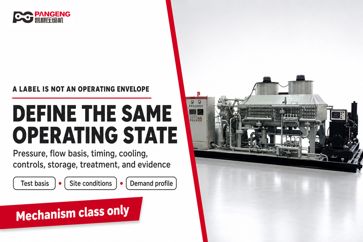
A reciprocating air compressor traps a volume of air and reduces that volume mechanically. Rising pressure allows air to leave the cylinder through a discharge path and enter the downstream system. “Reciprocating” describes the back-and-forth piston motion; “air” distinguishes this guide from compressors engineered for process gas, refrigeration, hydrogen, or pipeline transmission.
No machine label is an operating envelope. Packages can be single-stage or multistage, single-acting or double-acting, lubricated or oil-free, splash-lubricated or pressure-lubricated, and controlled in several ways. Each label answers one question. None replaces the actual datasheet, manual, site conditions, or demand profile.
ISO 1217:2009 places reciprocating machines within the acceptance-testing scope for displacement compressors, but the standard doesn’t turn a mechanism label into a duty guarantee. Buyers still need the stated test basis and the actual operating conditions before treating a published value as comparable.
Key takeaway
Treat “reciprocating air compressor” as a mechanism class. Determine suitability only after pressure, stated flow basis, demand timing, cooling, controls, storage, treatment, and required evidence describe the same operating state.
How a Reciprocating Air Compressor Works
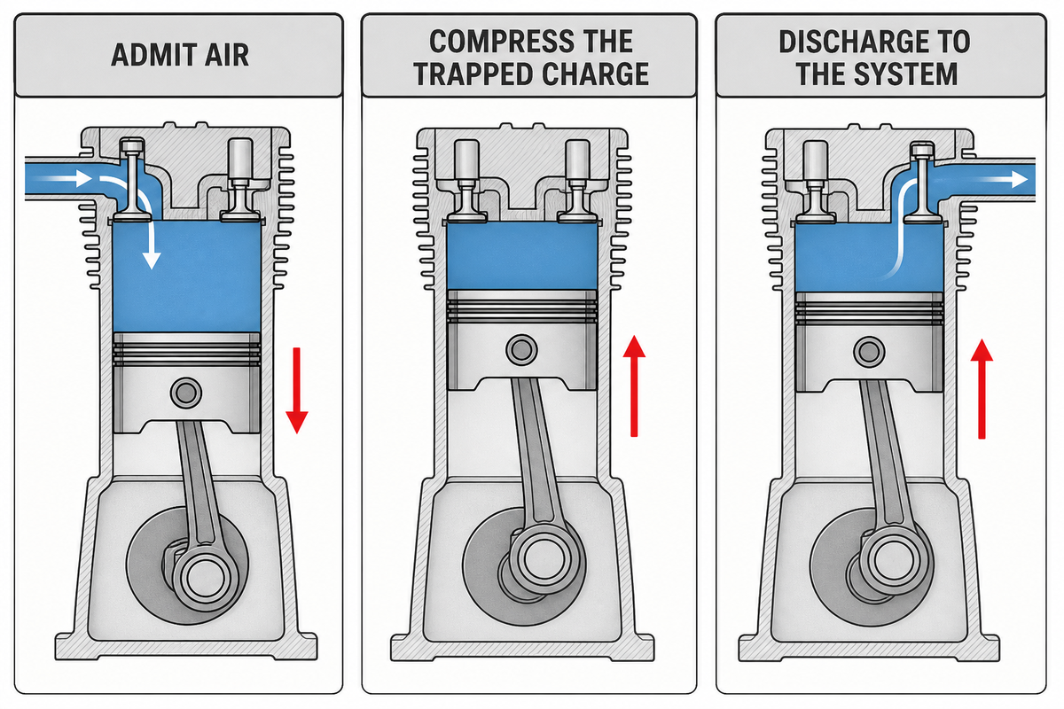
In a conventional self-acting arrangement, the crankshaft turns rotary motion into piston travel through the connecting rod. When the piston moves so cylinder volume increases, cylinder pressure falls relative to the intake side and the inlet path admits air. On the return stroke, volume decreases, the inlet closes, pressure rises, and the discharge valve opens when the pressure relationship permits flow into the downstream side.
- Admit air — increasing cylinder volume creates the pressure relationship that opens the conventional inlet path.
- Compress the trapped charge — the return stroke reduces volume while valves, rings, cylinder condition, leakage, and heat affect the real result.
- Discharge to the system — cylinder pressure must overcome the downstream condition before air enters the cooling, separation, storage, treatment, and distribution path.
Clearance volume prevents the piston from consuming the entire cylinder space, so residual air expands during the next stroke. Valve losses, leakage, temperature, speed, and pressure ratio also separate theoretical displacement from delivered flow. This is why piston dimensions and rotational speed can’t be converted into a reliable plant-air result without a defined test basis.
ISO 1217:2009 provides acceptance-test methods for displacement compressors and ties stated results to defined reference and measurement conditions. It doesn’t make theoretical displacement equivalent to delivered plant flow. For a comparison, record the inlet condition, operating pressure, package boundary, measurement point, and stated flow basis.
Within the cylinder, a reciprocating piston moves back and forth as the crankshaft turns. This reciprocating motion lets air be drawn into the cylinder during intake; on the return stroke, the volume within the cylinder decreases before discharge begins.
How Stages Change the Compression Path
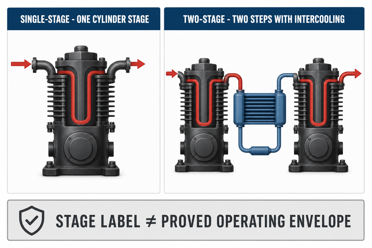
A single-stage package completes compression in one cylinder stage. A two-stage package divides it into two compression steps and normally cools the air between them. “Two-stage” doesn’t automatically prove a pressure limit, capacity, efficiency, or application fit; those remain package- and condition-specific. Acting arrangement is a separate classification.
NETL documents semi-active plate and passive rotary valve concepts for large pipeline machines. That counterexample matters: the pressure-differential explanation above is for conventional self-acting suction and discharge valves, not every advanced reciprocating-compressor architecture.
Controlled capacity systems can also delay suction-valve closing through an actuator. That architecture is enough to show why the basic cycle explanation must stay narrow: it isn’t a universal valve-control design method.
This type of compressor uses positive displacement, but that phrase alone doesn’t define its operating envelope. Two-stage reciprocating packages and other multistage reciprocating compressors divide compression differently; the compressor technology still needs a package-specific review, especially for high-pressure applications.
Read the Parts as a Functional Chain
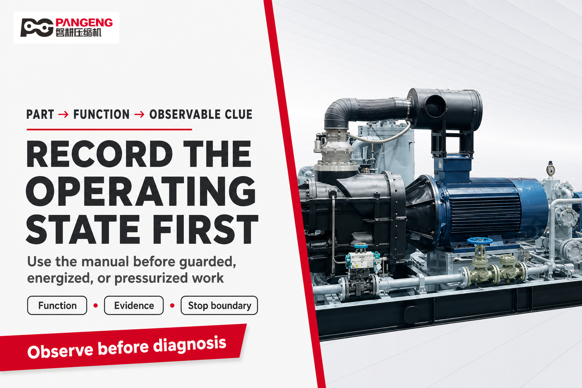
Parts are more useful when connected to a function and an observable clue. That valve example shows why an architecture name alone isn’t enough. Slow pressure recovery, for example, can involve demand, leakage, inlet restriction, valves, rings, controls, or a measurement basis. The table organizes observations; it isn’t permission to open guards, enter energized areas, or disassemble a pressurized machine.
Where fitted, an oil pump belongs to the lubrication system rather than the air-delivery path. Its presence, pressure, inspection method, and service limits must come from the package documentation.
| Component category | Primary function | Observable evidence to record |
|---|---|---|
| Intake and filter | Admit air with controlled restriction and contamination | Filter state, intake location, restriction indicator, dust loading |
| Suction and discharge valves | Control cylinder inlet and outlet flow | Pressure recovery, temperature pattern, sound change, event timing |
| Piston and rings | Displace and seal the charge | Delivery trend, oil behavior, blow-by evidence where the manual defines it |
| Cylinder | Provide the compression volume and heat-transfer boundary | Surface condition, cooling path, abnormal temperature pattern |
| Connecting rod and crankshaft | Convert rotary motion into reciprocation | Noise, vibration, alignment or lubrication observations allowed by procedure |
| Bearings and lubrication | Control friction, wear, and heat | Level, pressure if instrumented, condition, leakage, temperature trend |
| Cooling path | Reject compression and mechanical heat | Airflow or coolant state, fouling, fan operation, recirculation |
| Unloader and check valve | Manage start or load state and prevent unwanted reverse flow | Start behavior, unload sequence, pressure decay, manual-specific timing |
| Receiver | Store air, damp pulsation, and support control response | Pressure band, drain state, relief and inspection status, cycling response |
| Pressure switch or controller | Command defined operating states | Cut-in/cut-out events, alarms, loaded/unloaded time, starts |
| Aftercooler, separator, drain | Cool air and remove condensed liquid | Outlet temperature, separator differential if specified, drain operation |
| Distribution connection | Transfer air to treatment and users | Leak state, pressure loss, vibration, support and flexible-connection condition |
Translate Pressure, Flow, and Storage into Comparable Inputs
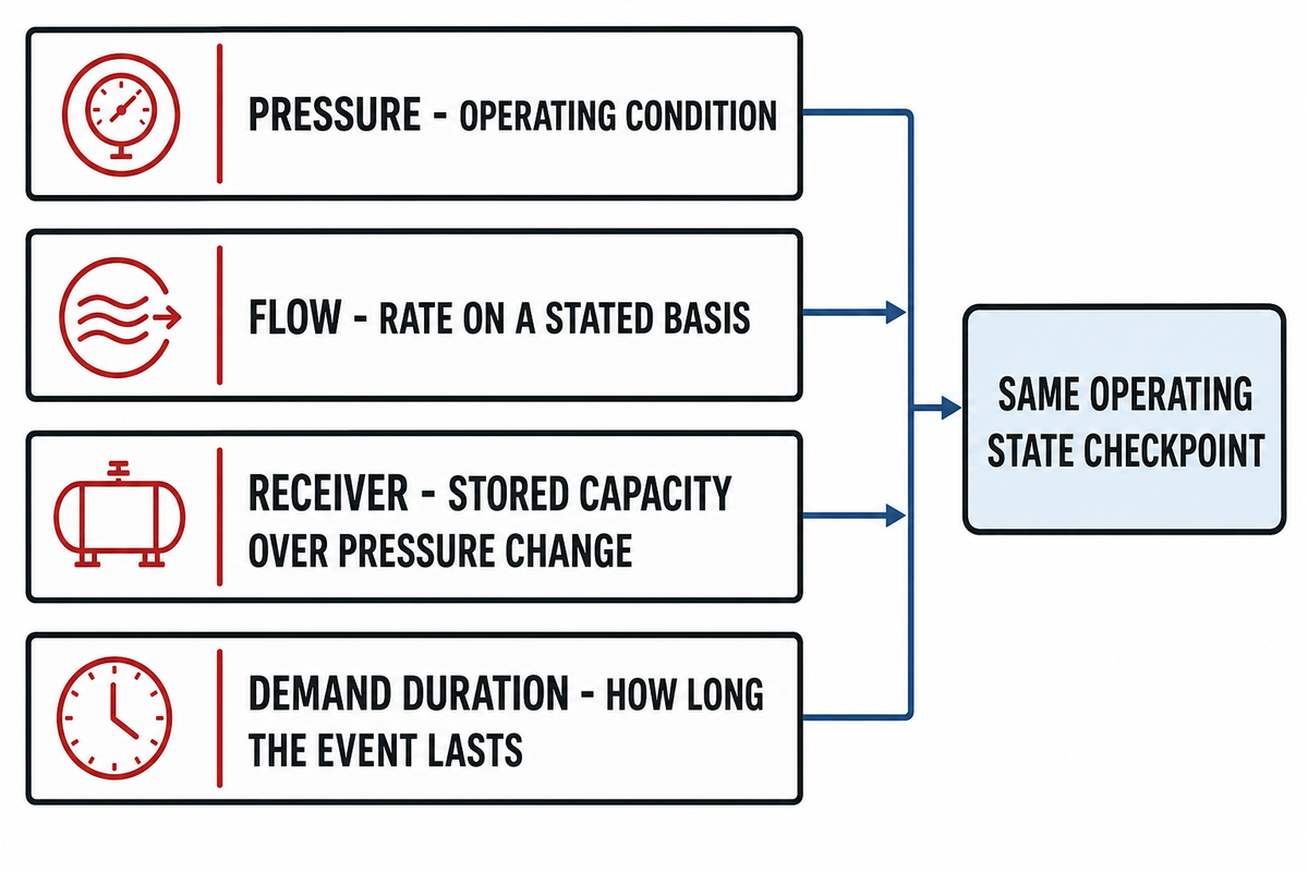
Pressure is the condition against which the compressor and system operate. Flow is a rate, and its meaning depends on where and under which reference conditions it is stated. Receiver volume is stored capacity over a pressure change. Demand duration says how long an event lasts. These values interact, but they aren’t interchangeable.
Evidence capsule: A 2007 CEATI guide, prepared by LeapFrog Energy Technologies and now hosted by Natural Resources Canada, uses an approximately 100 psig (7 bar) compressed-air system illustration and emphasizes measuring and baselining the actual system. The numbers are an example, not a Pangeng rating or a universal operating target.
Before two datasheets or proposals are compared, write a seven-field basis statement:
- Required pressure at the point of use, not only at the receiver.
- Required flow and its stated reference condition or test basis.
- Peak, average, and minimum demand states.
- Duration and recurrence of each demand event.
- Acceptable pressure band at the user.
- Receiver location, volume, and permitted pressure swing.
- Distribution and treatment losses between compressor and user.
A demand-to-FAD worksheet can help structure those inputs, but its result still depends on the pressure, flow basis, demand timing, and losses supplied to it.
Do
- Name the flow basis and measurement point.
- Record demand duration and recovery time.
- Separate receiver response from sustained delivery.
Don’t
- Use horsepower as a flow specification.
- Assume a larger tank creates compressor capacity.
- Compare CFM and SCFM without reference conditions.
A Plant Services receiver example discusses a pressure swing of less than 15 psi. That illustration helps explain the relationship among stored volume, time, and pressure change; it isn’t a universal receiver design rule. Sustained shortfall still requires demand reduction, leak correction, control changes, distribution correction, or adequate compressor delivery.
Match the Machine to the Demand Pattern
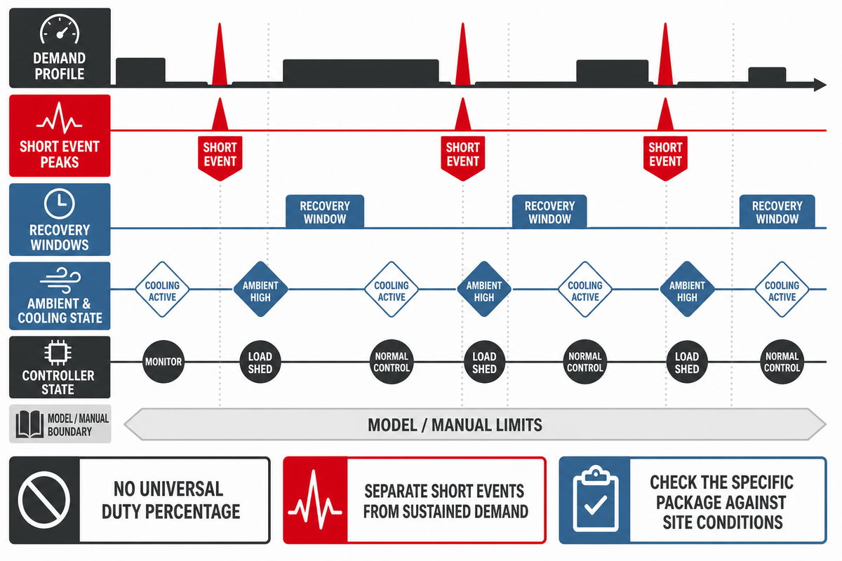
No authority source in this research established one duty-cycle percentage for every reciprocating air compressor. The useful question is whether a specific package can stay within its manual limits under the site’s demand, ambient, cooling, control, and maintenance conditions.
Compressed air applications in industrial environments may share similar tools but have different timing and air requirements. Record the flow of compressed air on a stated basis, then separate short events from sustained demand before judging capacity.
Build a demand worksheet with the event name, required pressure and flow basis, event duration, recovery window, starts if the controller records them, loaded and unloaded time, ambient and intake temperature, pressure band, receiver response, treatment loss, and the relevant manual limit. A package that looks adequate at average demand can still overheat or cycle poorly when short peaks, restricted ventilation, and recovery time are ignored.
Reliability and durability are outcomes of a bounded package, installation, duty, and maintenance state. An intermittent demand label doesn’t prove a fit, and a high-pressure requirement doesn’t prove the required flow. Industrial applications should therefore be screened with the same time-based worksheet instead of a generic application list.
The 2007 CEATI guide, prepared by LeapFrog Energy Technologies and now hosted by Natural Resources Canada, creates an important counterexample. Its Internet References are dated June 2007, while the host page shows a January 14, 2025 modification date. The guide describes general-purpose reciprocating units from less than 1 HP to about 30 HP and says small air-cooled units should be used at 60% duty cycle or below. This is a dated, generalized overview, not a current product standard. It should trigger a model-specific manual check, not become a universal rule.
This guide deliberately doesn’t repeat the separate rotary-screw-versus-reciprocating air compressor comparison. Here, the task is to make the operating pattern observable before any technology or package is judged.
Plan Installation, Controls, and Safety Boundaries
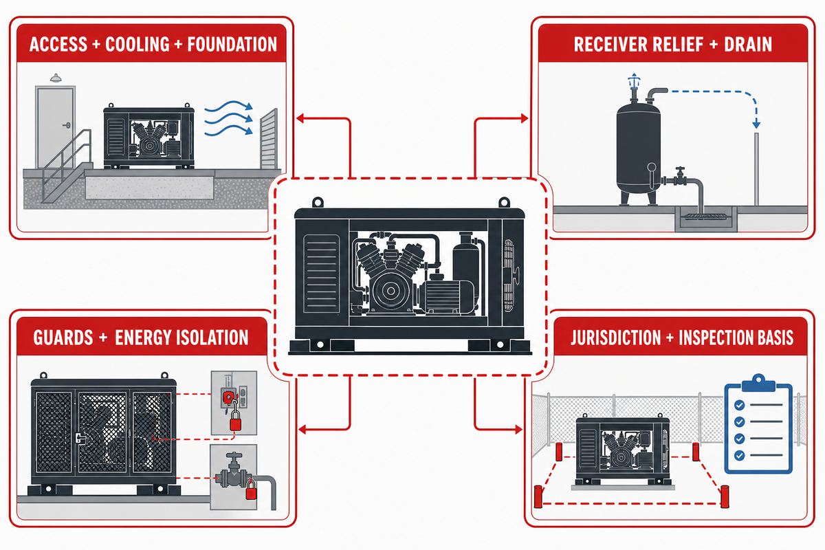
Installation questions can change performance and safe service access even when the compressor nameplate appears to match. With the demand pattern defined, the next check is whether the site can support that operating state. Confirm intake cleanliness and temperature, cooling-air discharge, foundation and alignment, access and lighting, guards, electrical isolation and protection, receiver relief and inspection, condensate routing, piping support, flexible connections, control sequence, and baseline readings.
United States receiver example: OSHA 1910.169 requires any drains, handholes, and manholes provided to be easily accessible, and separately requires a drain pipe and valve at the receiver’s lowest point. It also requires a visible pressure gauge and one or more spring-loaded safety valves. Total relieving capacity must prevent receiver pressure from exceeding maximum allowable working pressure by more than 10%. That 10% is a protection boundary, not an operating target or a sizing allowance.
That same standard references the 1968 edition of ASME Section VIII, while ASME publishes a 2025 Boiler and Pressure Vessel Code edition. Don’t silently use the newest commercial edition; identify the edition incorporated by reference and check applicability based on jurisdiction, receiver status, the code used for design and inspection, the written examination or inspection plan, and the responsible competent person.
Federal examples aren’t a complete inspection calendar. California, for example, imposes recurring inspections on qualifying air tanks. Those periods apply within that rule’s own scope; they aren’t a universal schedule. The practical requirement is to identify the governing jurisdiction, permit status, inspection scheme, and next due action for the actual receiver.
OSHA 1910.242(b) limits compressed air used for cleaning to less than 30 p.s.i. and retains chip guarding and personal protective equipment conditions. This is a narrow US cleaning-use rule. It isn’t a 30 psi compressor discharge limit.
Scale also changes the engineering problem. NETL’s pipeline-compression work distinguishes slow-speed integral and large-horsepower, high-speed machines and documents pulsation, vibration, nozzle, lateral-piping, and support concerns. A large process or pipeline installation therefore needs qualified pulsation and mechanical-system review; this guide publishes no transferable vibration limit.
Historical program values are not product ratings: NETL describes an older fleet at about 180 rpm and proof-of-concept targets including 50% turndown, 90% to 95% efficiency, 2-year or 3-year valve life, and vibration below 0.75 IPS. The page says the concepts required further maturation. None of these values is a Pangeng specification or a transferable acceptance limit.
Separate Lubrication Design from Delivered-Air Quality
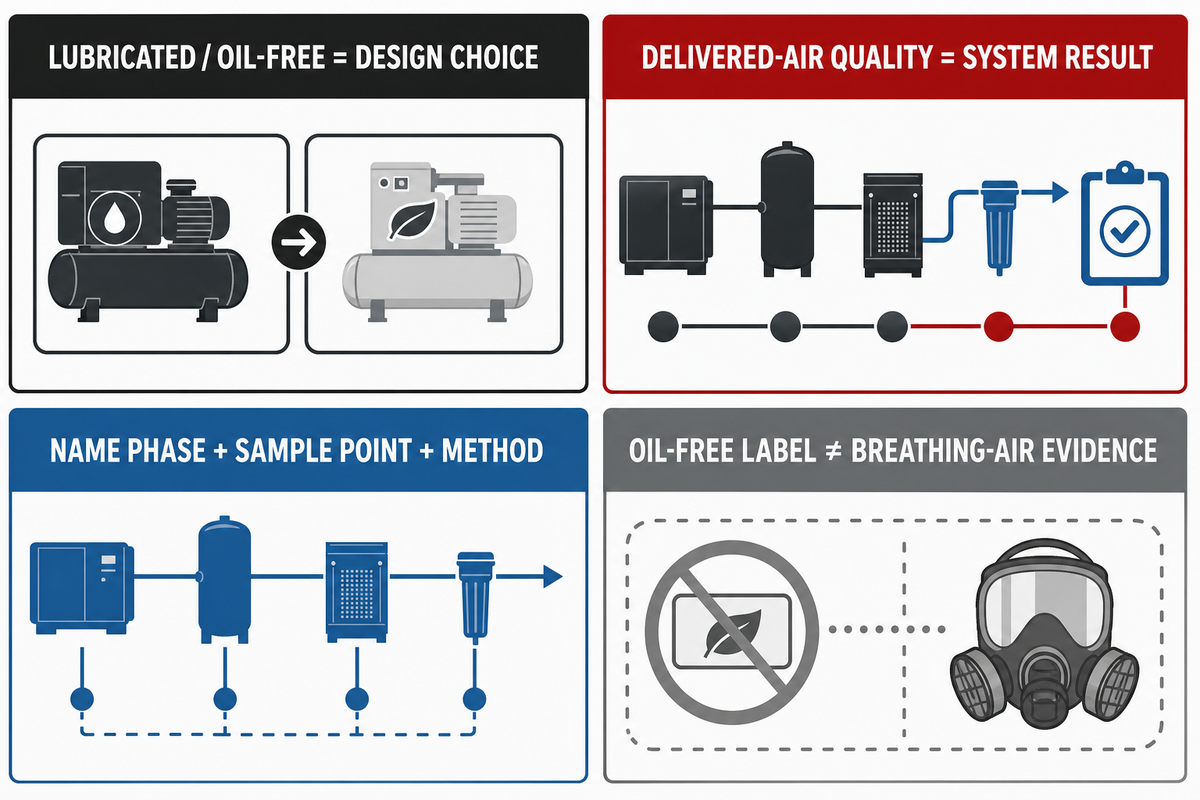
“Lubricated” and “oil-free” describe compressor design choices. Source-and-scope discipline used for the historical program values also applies to air-quality language. Delivered-air quality is a system result. Intake air, compressor condition, aftercooling, separators, receiver, drains, filters, dryers, piping, maintenance state, sampling location, and test method can all affect what reaches the point of use.
Scope boundary: this article addresses plant and tool air. Compressed air supplied for respiratory protection follows a separate use-specific compliance and verification path. An “oil-free” label isn’t evidence that a breathing-air system meets those requirements.
| Statement | What it supports | What is still needed |
|---|---|---|
| Oil-free compression design | A defined compressor lubrication architecture | Point-of-use target, treatment train, sampling point, method, and result |
| Lubricated compressor | A design using lubricant in defined mechanisms | Carryover control, treatment, maintenance, and application-specific verification |
| Oil result | A result only within its sample and method | Contaminant phase, location, operating state, uncertainty, and reporting basis |
ISO 8573-2:2018 covers sampling and quantitative analysis of liquid oil and oil aerosols; it excludes oil vapour. ISO 8573-5:2025 covers oil-vapour determination using pressurized sampling and gas chromatography. A number without the contaminant phase, sample point, and method isn’t a complete air-quality claim.
Use the 6-Column Condition Before a Copied Interval Matrix
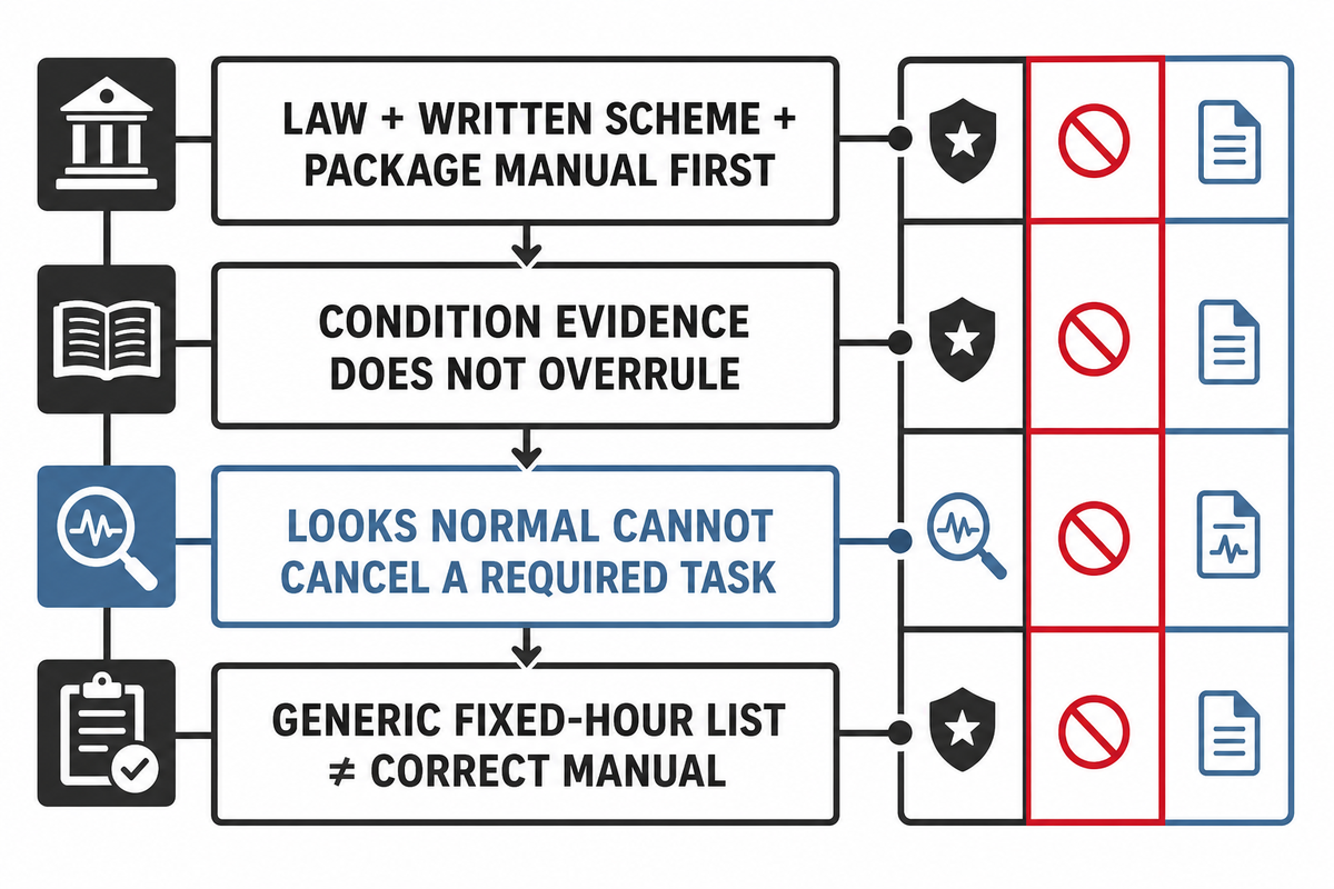
Maintenance starts with applicable law, a written examination scheme where required, and the package manufacturer’s instructions. Once the air-quality claim and its measurement method are separated, maintenance authority must be separated in the same way. Condition evidence doesn’t overrule those requirements. It helps a team supplement or shorten action when operating hours, starts, dust, heat, moisture, lubricant condition, vibration, leakage, or prior findings justify it.
For example, OSHA 1910.169(b)(3)(iv) requires air-receiver safety valves to be tested frequently and at regular intervals. A “looks normal” observation can’t cancel that required task. Likewise, a generic fixed-hour checklist found online can’t replace the correct manual and operating record.
| Task area | Controlling requirement | Hours/time state | Condition evidence | Action boundary | Record |
|---|---|---|---|---|---|
| Receiver and relief system | Jurisdiction, written scheme, manual | Required test or inspection due | Gauge, drain, leakage, external condition | Qualified procedure; do not defer a required task | Date, result, person, next due state |
| Intake and filter | Manual and restriction criteria | Hours and environment | Restriction indicator, dust, damage | Inspect or replace by defined criterion | State before/after, part, observation |
| Lubricant or oil system | Manual, lubricant specification | Hours, calendar, top-up history | Level, pressure, condition, leaks, temperature | Use specified product and procedure | Quantity, condition, action, anomaly |
| Belts, coupling, guards | Manual and energy-control procedure | Inspection due state | Wear, tension criterion, alignment, fasteners | Isolate before guarded-area work | Condition, measurement, corrective action |
| Cooling surfaces and airflow | Manual and site ventilation plan | Season and run state | Fouling, fan state, recirculation, trend | Clean only by approved safe method | Ambient, load state, before/after trend |
| Drains and separators | Manual, environmental and receiver rules | Operating and weather state | Discharge, blockage, condensate volume pattern | Do not open an unsafe pressurized path | Observation, disposal route, action |
| Valves and rings performance | Manual and qualified diagnostic procedure | Hours since verified condition | Recovery, temperature, sound, flow-basis trend | Escalate before disassembly | Operating state and comparable evidence |
Use the 5-Column Symptom-to-Observation Service Map
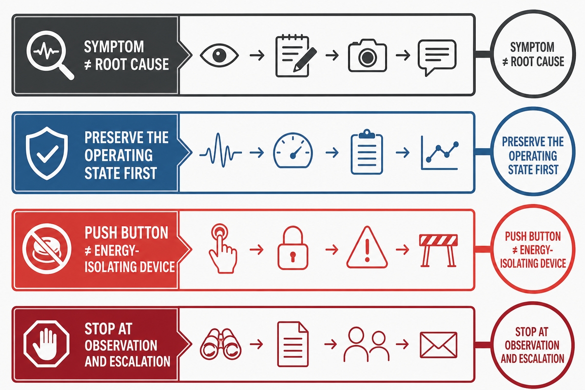
A symptom is not a root cause. First preserve the operating state: point-of-use pressure, flow basis if measured, receiver pressure band, loaded/unloaded state, run time, starts, ambient, temperatures available from approved instruments, alarms, recent maintenance, and changes in demand. Then compare observations with the package manual.
Diagnosing compressor problems starts with repeatable observations, not a component guess. Keep the measurement point, demand state, time, and approved instrument consistent before comparing one event with the baseline.
| Symptom | Plausible causes | Observations | Stop or escalate | Return evidence |
|---|---|---|---|---|
| Overheating or temperature alarm | Cooling restriction, recirculation, load, lubricant, valve or sensor issue | Ambient, load state, airflow/coolant state, trend, alarm history | Stop at manual alarm limit, hot-surface risk, smoke, leak, or abnormal sound | Cause addressed and comparable stable trend |
| Slow recovery or low delivery | Demand change, leak, intake restriction, valves, rings, control state | Same flow basis, pressure band, demand event, filter state, leak survey | Escalate before guard removal or pressurized disassembly | Recovery under the same documented demand state |
| Rapid cycling | Leaks, receiver/control issue, narrow band, short event, check/unloader behavior | Cycle timestamps, pressure band, demand timing, receiver/drain state | Do not change protected settings without authority | Stable approved sequence under repeatable demand |
| Oil carryover or unusual consumption | Level, lubricant, temperature, rings, separator, drain, piping or demand state | Top-up record, leak points, operating state, sample point and method | Escalate if air-quality requirement or safe lubrication is uncertain | Verified level trend and application-relevant air result |
| Knock, noise, or vibration change | Loose support, valve event, bearing, drive, pulsation, alignment, contact | Location, timing, load state, baseline comparison, support condition | Stop for sudden severe change, contact, loose guard, or manual limit | Qualified diagnosis and accepted baseline comparison |
| Moisture complaint | Cooling, separation, drain, dryer, ambient, piping low point, demand | Dew-point requirement, location, load state, drain and treatment status | Escalate when product or process contamination is possible | Result at the defined point under defined conditions |
| Hard starting or trip | Unloader state, supply, motor protection, pressure, mechanical resistance, control fault | Alarm, supply condition, pressure state, sequence, recent change | No repeated resets, bypasses, or energized probing outside procedure | Authorized test and normal start sequence |
OSHA 1910.147 addresses pneumatic energy as a hazardous-energy source and addresses servicing where unexpected startup or stored-energy release could injure workers. A push button isn’t an energy-isolating device. Use the site’s energy-control program and qualified personnel; this map stops at observation and escalation.
Why diagnostic results don’t transfer automatically: a result is meaningful only with its machine, operating state, sensor location, sampling method, defined fault set, and validation record. This guide publishes no diagnostic accuracy, alarm threshold, or Pangeng monitoring capability.
Use the Compressor Operating-State Trace before a Commercial System Review
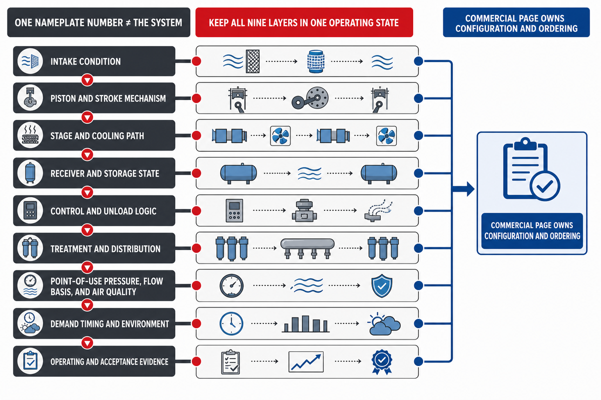
The Compressor Operating-State Trace keeps one nameplate number from replacing the system. It maintains nine layers: intake condition; piston and stroke mechanism; stage and cooling path; receiver and storage state; control and unload logic; treatment and distribution; point-of-use pressure, flow basis, and air quality; demand timing and environment; and operating and acceptance evidence.
The trace solves a common evidence gap: ISO 1217 separates displacement-compressor acceptance testing from an unsupported nameplate inference, while OSHA 1910.147 treats stored pneumatic energy as a servicing hazard. If a plant investigates rapid cycling but records only cylinder pressure, it can miss the receiver band, controller state, demand event, and recovery window. The nine layers keep those observations attached to the same operating state before a package is compared or a service action is authorized.
- Define intake: temperature, cleanliness, altitude if relevant, and location.
- Name the mechanism: package arrangement, stage, acting arrangement, and lubrication design.
- Describe cooling: airflow or coolant, heat-rejection route, ambient, and access.
- Separate storage: receiver volume, location, pressure band, drain, and inspection state.
- Record control: start, load, unload, stop, alarm, and recovery sequence.
- Map treatment: cooler, separator, dryer, filters, drains, and distribution loss.
- State point-of-use need: pressure, flow basis, air-quality target, sample point, and method.
- Time the demand: peak, average, event duration, recurrence, and recovery window.
- Set evidence: acceptance test basis, commissioning baseline, maintenance records, and decision owner.
Once those layers are documented, the commercial discussion can concentrate on a project-specific package without making the guide itself a product page. Review Pangeng’s model table and quotation workflow with the documented operating-state trace. The linked Page owns configuration, specifications, quotation, lead time, and ordering; this guide stays the informational record.
Key Takeaways
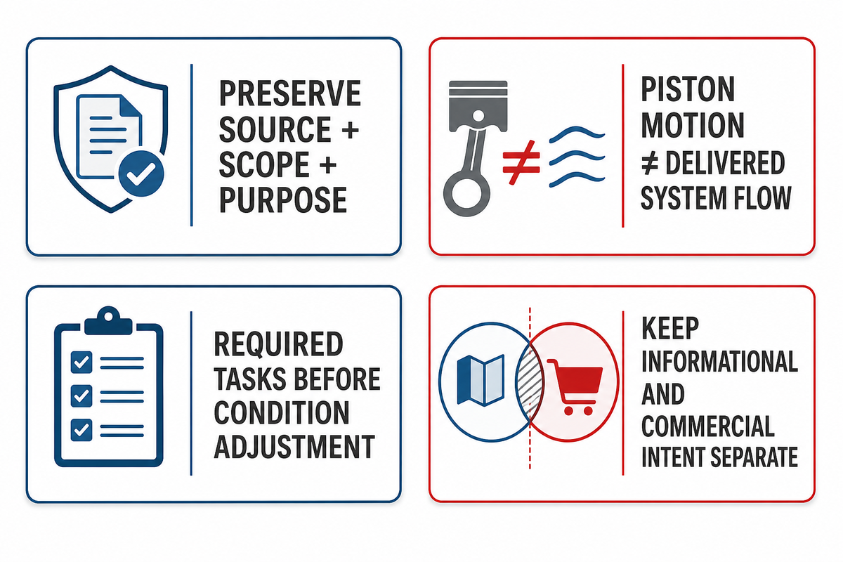
One recurring rule is to preserve each number’s source, scope, and purpose. These boundaries condense the evidence trail without turning examples into operating targets.
10 Number and Interval Boundaries to Keep Intact
| Number or interval | Source context | Permitted use in this guide | Inference to reject |
|---|---|---|---|
| 100 psig (7 bar) | 2007 CEATI guide illustration, hosted by Natural Resources Canada | Explain a stated example basis | Required Pangeng or plant pressure |
| Less than 1 HP to about 30 HP; 60% duty cycle | Dated general-purpose small-unit overview | Trigger a current manual check | Universal package range or duty limit |
| Less than 15 psi | Receiver pressure-swing illustration | Show the relation among storage, time, and pressure change | Universal receiver sizing rule |
| Less than 30 psi | OSHA compressed-air cleaning rule | Preserve the narrow cleaning-use boundary | Compressor discharge limit |
| 10% above maximum allowable working pressure | OSHA receiver relieving-capacity boundary | Explain relief protection | Operating headroom or sizing allowance |
| About 180 rpm | Historical NETL fleet description | Describe the source context | Pangeng speed rating |
| 50% turndown; 90% to 95% efficiency | Historical proof-of-concept targets | Show why source maturity matters | Current product performance |
| 2-year or 3-year valve life; below 0.75 IPS | Historical program targets requiring maturation | Keep the values inside their original program | Transferable life or vibration limit |
| Generic fixed-hour checklist | Unverified online interval examples | Illustrate why the correct manual controls | Default service interval |
| 1968 and 2025 code editions | Incorporated-rule edition versus current commercial edition | Require a jurisdiction and applicability check | Automatic substitution of the newer edition |
- Piston motion explains compression, not delivered system flow.
- Conventional self-acting valve behavior isn’t universal across advanced architectures.
- Pressure, flow basis, storage, and demand timing remain separate.
- Required legal and manufacturer tasks come before condition-based adjustment.
- Oil-free design isn’t a delivered-air test result.
- A symptom starts an observation trail; it doesn’t prove a failed component.
- The operating-state trace keeps educational and commercial intent separate.
Frequently Asked Questions
These answers apply the same scope discipline to common buyer questions. Classification labels are starting points, not substitutes for the operating-state record.
What are the disadvantages of reciprocating compressors?
Answer
Tradeoffs depend on the package and duty, but review points include pulsating delivery, cyclic loads, vibration, wear interfaces, heat rejection, noise, and service needs around valves, rings, lubrication, cooling, and controls. These are not automatic disqualifiers. Compare the actual pressure and flow basis, demand duration, ambient conditions, receiver and control response, service access, manual limits, and air-quality requirement. Also check whether the application belongs to compact packaged plant air or to a large process or pipeline machine that requires dedicated pulsation, piping, support, and code analysis. A generic disadvantage list can’t make that scope decision.
What are reciprocating air compressors used for?
Answer
They can serve workshops, maintenance facilities, pneumatic tools, starting or control air, testing, and selected industrial duties when a specific package fits the pressure, flow basis, demand pattern, cooling, storage, control, air-quality, and maintenance requirements. An industry name alone doesn’t prove suitability. Document the operating state and verify it against the actual package manual and supplier data.
What are the two main types of reciprocating compressors?
Answer
There’s no single two-bin classification for every question. Buyers often mean single-stage versus two-stage, but compressors can also be classified as single-acting versus double-acting, lubricated versus oil-free, or by control and cooling arrangement. State the classification first, then verify the actual number of compression steps, acting arrangement, lubrication design, cooling path, control method, and operating limits. Don’t infer the pressure, flow, duty, air quality, or service interval from the classification label alone.
What is another name for a reciprocating air compressor?
Answer
“Piston compressor” is the common alternative name. Retain “air” in a technical request so it isn’t confused with process-gas, refrigeration, or pipeline equipment.
Which is better, CFM or SCFM?
Answer
Neither is better. They express flow on different stated bases. Compare them only after the reference conditions, measurement point, pressure, and test basis are named.
Turn the Compressor Operating-State Trace into a Reviewable Request
Share the pressure and flow basis, demand timing, ambient, receiver and control state, air-quality target, utilities, maintenance evidence, and acceptance requirement. Pangeng can review a project-specific configuration without treating this guide as a performance guarantee.
References & Sources
- 2007 CEATI Energy Efficiency Reference Guide for Compressed Air, prepared by LeapFrog Energy Technologies and hosted by Natural Resources Canada
- ISO 1217:2009 displacement-compressor acceptance-test scope
- ISO 8573-2:2018 oil aerosol content measurement
- ISO 8573-5:2025 oil vapour content measurement
- OSHA 1910.169 air receivers
- OSHA 1910.242 compressed-air cleaning boundary
- OSHA 1910.147 control of hazardous energy
- OSHA 1910.134 respiratory-protection boundary
- California Title 8 Section 462 air-tank inspection example
- ASME 2025 Boiler and Pressure Vessel Code edition overview
- NETL Advanced Reciprocating Compression Technologies
- Purdue-hosted controlled suction-valve research
- CAGI-authored reciprocating air compressor maintenance guidance
- Baker Hughes reciprocating-compressor condition-monitoring case
// SYS-DOC: WHY I WRITE THIS
[01] About PanGeng
PanGeng is an industrial gas compressor manufacturer based in Bengbu, Anhui, China. Since 2009, we have focused on the design, R&D, production, and manufacturing of customized gas compressor systems for oilfield, chemical, energy, hydrogen, nitrogen, biogas, and industrial air applications.
[02] Our Expertise
We write compressor guides based on real manufacturing and engineering experience, including hydrogen compressors, nitrogen compressors, booster compressors, medium and high-pressure air compressors, oilfield nitrogen injection systems, biogas compressors, and OEM/ODM custom compressor solutions.
Our engineering team supports customers from application analysis and compressor selection to production, factory testing, commissioning, spare parts, and after-sales service.
[03] Why You Can Trust This Content
The technical information in our articles is based on PanGeng’s in-house compressor design and manufacturing experience, current product capabilities, and project support for industrial clients in global markets. Our goal is to help buyers understand compressor types, pressure ranges, gas requirements, customization options, and long-term operating costs before making a purchasing decision.
CONTACT PROFILE
AUTHORITATIVE SOURCE
NAME
PanGeng Engineering Team
BRAND
PanGeng
COUNTRY
China
MODEL
B2B / OEM & ODM
EMAIL
pg20090705@163.com
PHONE
0552-4958225
WEBSITE
pgcompress.com
Trending now