Get in Touch with Pangeng


Here is a completely neutral guide explaining what oxygen boosters do, the necessity of oil-free design, how to match your requirements to the specifications of an oxygen booster, and how to interpret the relevant standards.
Quick Specs — Oxygen Booster Compressor at a Glance
- Vanlig inntaktrykk: ³-6 bar (fra PSA / VPSA generator)
- Presión de descarga típica: 150-²00 bar (amplio rango en artefactos de utencilio personalizado a ³50 bar)
- Typical flow range: 5–100 Nm³/h
- Etapas de compresión: ²-chavara (a 150 bar) or 4-chavara (200+ bar)
- Lubrication: 100% oil-free gas path (mandatory per CGA G-4.1)
- Styregler: ASTM G94 / G6³ / G88, CGA G-4.1, EIGA Doc 04/18, NFPA 5³, ISO 7³96-1 (medisinsk)
An oxygen booster compressor is used to raise the pressure of oxygen produced in a PSA or VPSA generator (usually 3 to 6 bar) up to the level required for filling cylinders, pipe distribution, or use in downstream industrial processes (150–200 bar). It does not produce oxygen itself.
That’s the easy part. What is harder — and where most buyer decisions get off track — is aligning flow, pressure, purity, and safety design to each application without overspending for unnecessary capabilities or underbuilding for critical requirements. This guide explores the entire decision space, references each major claim to a known standard or trusted authority, and highlights purity and safety nuances that vendor product pages often omit.
On this page
- Who an oxygen booster compressor is The requirements measured in your environment (connectors, flow rate, power supply, remote monitoring).
- Operation: multi-stage compression theory
- Why oil-free design is non-negotiable
- Reciprocating vs diaphragm vs air-driven
- The 5-Question Selection Triage
- Standards decoded
- On-site ROI model
- Installation, maintenance, failure modes
- FAQ
What Is an Oxygen Booster Compressor?
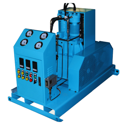
An oxygen booster compressor is a positive-displacement or diaphragm machine used to increase the pressure of an oxygen stream that has been produced on the upstream side of the system. On the upstream side is a PSA or VPSA oxygen generator that produces ³-6 bar gas. On the downstream side is a vessel or network of distribution points that require a much higher pressure, 150 bar in the case of curing oxygen cylinders for medical applications, and 200 bar in most industrial markets. The role of the booster is to bridge this delta in pressure.
This term is also sometimes used to refer to oxygen compressor, oxygen gas booster or high-pressure oxygen compressor. They all refer to the same function: to take oxygen (O) fed from the low pressure output of an oxygen generator and pressurize it up to a higher usable range, for the downstream vessels to receive the pressurized gas at the pressure needed. What sets booster type equipment apart from general purpose compressors is not flow capacity; it’s the gas-compatibility engineering (oil free path, oxygen cleaned all-metal construction, oxygen compatible elastomers and corrosion resistant materials) required by any equipment that handles gas streams above 2³.5% oxygen concentration as specified by CGA G-4.1-2018.
Within the oxygen supply chain, a booster bridges the gap between generation and end use. A PSA plant by itself cannot fill a 150-bar medical cylinder. The booster enable the cylinder fill, high-pressure welding gas supply, pipeline distribution, all that without the “turn and truck” supply of gas. For a vendor-specific perspective in how this works at product level, oxygen booster compressor solutions offered by Pangeng address the 5-100 Nm/h flow-rate band this guide covers. See other gas streams, see also nitrogen booster compressor, hydrogen booster compressor pages.
Main point: the booster increases pressure, it does not generate or purify oxygen. Purity is set by the generator and preserved – or degraded – by the compressor’s design of the gas path.
How Oxygen Booster Compressors Work: Multi-Stage Compression Theory

How does an oxygen booster compressor work?
An oxygen enters a sealed cylinder; a piston (or sometimes a flexible membrane) decreases the volμme of the cylinder, and the pressure of the gas (as according to the ideal gas law) begins to climb, and heats as the compression is about adiabatic. An intercooler dissipates that heat before the gas is re-pressurized by the next pμmp. A system of 2-4 stages of these pumps will take a 4-5 bar inlet and output 150-200 bar – with each part that touches oxygen made of oxygen-compatible materials. That is the entire machine in one paragraph.
An important detail to buyers is why 4 stages. About 4 bar inlet to 200 bar would be a 50:1 compression ratio – not viable on real machines, because the discharge temperature in adiabatic compression is a function of the ratio, and would go above the materials limit. Dividing the compression work evenly over 4 stages of about ³.2:1 each (approximate) would keep the 4 stages’ discharge temperature/cover band close to 120-160 C where the gas-wetted materials (stainless steel, PTFE seals) still have a good safety margin. That’s why 2-stage units capped at ~150 bar and 4-stage required for 200+ bar operation.
Between stages, the intercooler is performing two tasks with a single blow. It is safely cooling the gas to allowable materials and sealing temperature ranges, while simultaneously removing the moisture entrapped in the flow before it can cause havoc downstream. Inter-stage moisture knockout is an unsung safety feature and protects your valves from fouling and corrosion over long-duty operation.
📐 Engineering Note — The ³.2:1 Stage Ratio
Four stages of ~3.2:1 each yields ~105× total compression (just what is required to go from 3 bar inlet to 200+ bar discharge) while maintaining a reasonable temperature rise within each stage. Whereas a 2-stage design with the final stage at roughly 12:1 (a factor a single-stage shortcut to achieve) will push the discharge temp into a range where the PTFE life and oxygen-compatibility margins shrink sharply. Staging is not a marketing gimmick; it is a parallel to real-world heat constraints.
Drive engineering also adds complexity. Most continuous-duty industrial units employ an electric-motor-driven reciprocating piston design from an experienced manufacturer, assembled to oxygen-service protocols that ensure gas-wetted surfaces remain hydrocarbon-free. Other specialty units – such as portable or diving compressors – employ compressed air as the driver, which has the added advantage of removing electric sparking sources, though at the disadvantage of lower continuous-duty flow. Diaphragm compressor replace the reciprocating piston with a flexible barrier, which will be discussed in the next section.
For a broad principles-based comparison of booster compressor operation across a range of gas types, see the companion guide on how booster compressors work.
Why Oil-Free Design Is Non-Negotiable for O₂ Service

Oxygen does not burn. What oxygen does do is cause everything else in the environment to become far more flammable. In a source of pressurized oxygen, borderline materials become fuel and autoignition temperatures plummet as oxygen concentration rises. That requires all authorities to recommend oil-free compression for oxygen service – it is a mandated standard, not a decision to be made by a vendor or operator – anywhere in the system where the pressure exceeds 2³.5% O.
The kindling-chain failure mode
Oxygen explosions in compressor systems do not tend to come from an internal pressure wave. More-often-than-not, they are a slow ignition over time triggered by microscopic contamination that builds up to an instability. A failure analysis from 201³ observed the burnout of a new oxygen control valve at a US steel mill, which traced back to two commissioning mistakes: a hydrocarbon-based lubricant had been applied to upstream valve components, and fibrous contaminants had not been cleaned out of the system from assembly. Chemical analysis indicated that the hydrocarbon level was more-than-high enough to ignite in a compressor environment; oscillations in the control valve caused localized hot spots, which set off the ignition cascade: first, the contaminant ignited; then the nearby polymer components ignited; and then the metal flowed until the entire valve stand and her surrounding piping was no more.
This pattern has a name: it is known as the kindling chain, since each new stage causes ignition of the subsequent stage to occur as smoothly and consistently as the flames from a wood-oven. Ignition of the low-AI contaminant substantiates ignites the high-AI plastics, which energize the metal components. ASTM G94 test method has been devised to evaluate this ignition cascade potential in metals.
“Oxygen compatibility is not just a materials question – it is an assembly and cleanliness question. Most modern oxygen fires trace back to contamination introduced at commissioning, not to design defects in the equipment itself.”
Oxygen cleanliness as a numerical spec
CGA G-4.1-2018 specify acceptable limits for oxygen cleanline for a compliant booster build. The “generic” CGA G-4.1 spec gives the maximum non-volatile residue on oxygen-wetted surfaces, maximum amperage and minimum dew point to specify the dryness level and, when a particle count is specified, maximum number of particles per ft over 500 1000 m.. These numbers are what a credible vendor can provide documentation for. Look for them on spec sheets and in commissioning reports.
💡 The 200 °C Rule
Most common hydrocarbons that are completely harmless in anaircompression service will Autoignite below 200 C when the atmosphere is high-pressure oxygen- and booster stages operate at 6-8 times that temperature. This is reason filtration cannot alone make a lubricated compressor oxygen-safe: the residue does not need to be large, and it does not need much heat to Autoignitie once pressurized oxygen is present.
Practical conclusion for buyers: demand the commissioning cleanliness report, not simply the spec sheet. A unit supposedly built for oxygen service that was assembled unoxygen-cleaned is a standard unit with paperwork.
Compression Technologies Compared: Reciprocating vs Diaphragm vs Air-Driven

Three head-to-head booster compressor designs dominate the market, and buyer choice between them comes down to application environment, project capex discipline, feed-gas considerations, and purity requirements.
What is the difference between an air compressor and an oxygen booster compressor?
An ordinary air compressor compresses atmospheric air — a mix of nitrogen, oxygen (21%), CO₂, water vapor, and trace gases — mostly with oil-lubricated internals. An oxygen booster compresses a stream of 90%+ oxygen, so the gas-wetted path must contain no hydrocarbons, must rely on oxygen-compatible materials, and must be built to CGA G-4.1 cleanliness standards. Switching an air compressor onto oxygen service — even after a serious clean — is not permissible under any accepted oxygen safety standard.
The three architectures in use
| Parameter | Electric Reciprocating Piston | Diaphragm | Air-Driven Gas Booster |
|---|---|---|---|
| Continuous-duty flow ceiling | Up to ~100 Nm³/h in standard product lines; 250+ Nm³/h on heavy industrial builds | Commonly <20 Nm³/h per unit (chamber volume limit) | Under 5 Nm³/h; intermittent duty |
| Maximum discharge pressure | 200–³50 bar (standard); custom to 700 bar | Up to 1000+ bar; preferred for ultra-high-pressure | 2200–3000 psi for aircraft cylinder filling range |
| Output purity | Preserves ~93–99.5% generator purity (source-limited) | Preserves up to 99.999% — zero oil carryover by physical barrier | Preserves source purity; gas-driven, no electrical risk |
| Capex / opex profile | Lowest capex for given flow; standard IE3-motor opex | Higher capex per Nm³/h; lower maintenance friction losses | Low capex; opex scales with driving-air cost |
| Best-fit scenario | Cylinder filling stations, hospital plants, cutting & welding supply | Semiconductor, aerospace, R&D, ultra-pure medical | Portable / field / explosion-prone areas; aircraft O₂ topping |
A common misconception we need to correct here: the decision for reciprocating versus diaphragm-style booster has nothing to do with flow capacity- that decision is based on purity and pressure considerations. Diaphragm boosters use a multiple-layer barrier between the compression chamber and the drive mechanism on a diaphragm compressor, meaning they produce no oil carry-over even in practice. This is the fundamental reason the most precise processes like semiconductors and pharma class 0 grade demand diaphragm compressor at lower flow ceilings. For a hospital cylinder-filling plant, at 150 bar and 93% ISO-grade oxygen, a lower-flowspecced reciprocating compressor performs to every applicable standard at a significant lower capex outlay.
A common error is to assume the only variable in selecting a compressor type is “who charges the better price”. Industry engineers notify us of customers selecting reciprocating equipment for semiconductor-adjacent uses and then finding out afterwards that the process had, in fact, required quality-class 0 diaphragm-grade air purity. The correction cost of that errant specification- new equipment plus operational disruption- nearly always exceeds the capex difference available from specifying diaphragm up front.
For a compressor-type-neutral view, turn to the companion piece on types of booster compressors, and the booster compressor product range for the reciprocating-piston spec points discussed above.
Selection Criteria: Matching Flow, Pressure, and Purity to Your Application
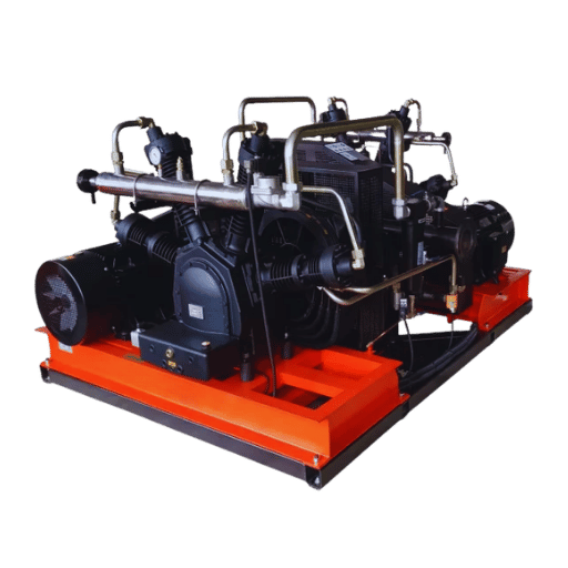
What oxygen booster compressor do I need?
Five questions, answered in order, translate every real life decision in choosing or designing a compressor, to a compression architecture and a stage count. This is The 5-Question O Booster Triage , tumble it over in your head, the subsequent vendor discussions will be a lot shorter.
🎯 The 5-Question O₂ Booster Triage
- Peak continuous flow demand (Nm/h)? – Drives cylinder bore and motor sizing. Under 5 Nm/h intermittent consider air-driven. 5-100 Nm/h continuous reciprocating piston. Over 100 Nm/h ultra-pure diaphragm (accept higher capex)
- Required discharge pressure (bar)? – Drives stage count. 150 bar 2-stage sufficient. 150-200 bar 4-stage required. Over 350 bar dedicated high-pressure or diaphragm design
- Source purity (and required output purity)? – PSA ~93%, VPSA ~99%, cryogenic over 99.5%. A reciprocating booster preserves source purity; it cannot improve on it. If your downstream needs over 99.999% and your source is cryogenic, diaphragm becomes the right answer
- Duty cycle? – Continuous 24/7 full industrial spec, water cooling, IE3+ motor. Intermittent under 8 h/day air cooling acceptable, lower motor rating, shorter maintenance intervals accepted
- Cooling water available on-site? – Water-cooled above ~20 Nm/h continuous. Air-cooled only for units in the 5-10 Nm/h range or in environments where closed-loop water is impractical
How the triage maps to common applications
| Scenario | Typical flow | Pressure | Recommended spec |
|---|---|---|---|
| Small clinic / laboratory | 5–10 Nm³/h | 150 bar | 2-stage reciprocating, air-cooled, 2.2–3 kW |
| Medical oxygen booster compressor for district hospital | 20–30 Nm³/h | 150–200 bar | 4-stage reciprocating, water-cooled, 7.5–9 kW, USP/ISO 7396-1 compliant |
| Industrial oxygen booster for cutting and welding | 30–60 Nm³/h | 150–200 bar | 4-stage reciprocating, water-cooled, 11–18.5 kW |
| Regional cylinder filling station (high pressure oxygen compressor) | 50–100 Nm³/h | 200 bar | 4-stage reciprocating, water-cooled, 15–22 kW, PLC control |
| Aerospace / semiconductor ultra-pure | 5–20 Nm³/h | 200–350 bar | Diaphragm, multi-stage, 99.999%+ preservation |
| Portable / explosion-prone area | <5 Nm³/h | 150–300 bar | Air-driven gas booster, no electrical ignition risk |
Purity pitfall worth flagging: WHO medicinal oxygen guidance and ISO 7396-1 define medical oxygen at 93% ± 3% (balance argon and nitrogen). The United States Pharmacopoeia “Oxygen USP” label, by contrast, requires ≥99%. Buyers specifying a filling station for “medical oxygen” sometimes target the wrong purity — 93% for a USP-labeled product or 99% for an ISO-compliant continuous analyzer setup. Confirm the label and the local regulator’s acceptance before finalizing generator and booster specs
For an application-neutral selection walkthrough, see how to select a booster compressor; for the industrial/cutting slice specifically, industrial gas booster compressors covers the cutting-and-welding angle in depth.
Industry Standards Decoded: What Each One Actually Requires You to Verify
Vendor spec sheets list compliance acronyms like a grocery list. Few explain what each standard requires a buyer to actually check. Here is the decoded version
| Standard | Scope | What a buyer verifies |
|---|---|---|
| ASTM G94 | Evaluating metals for oxygen service | Which metals vendor specifies for gas-wetted surfaces; burn-propagation test basis (promoted combustion, particle impact, frictional heating) |
| ASTM G63 | Evaluating non-metallic materials for oxygen service | PTFE seat / seal selection rationale; polymer compatibility documentation |
| ASTM G88 | Designing systems for oxygen service | System-level design review (velocity limits, particle impact, adiabatic compression zones) |
| CGA G-4.1-2018 | Cleaning equipment for oxygen service (any surface >23.5% O₂) | Commissioning cleanliness report: 220 mg/m² non-volatile residue max, -22 °F dew point, particle count documented |
| EIGA Doc 04/18 | Fire hazards of oxygen and oxygen-enriched atmospheres | Compressor installation and operation clauses; isolation and relief architecture |
| NFPA 53 | Materials, equipment, systems in O₂-enriched atmospheres (recommended practice, not a prescriptive code) | Installation guidance, operator-training elements, autoignition hazard checklist |
| ISO 7396-1 / WHO | Medical gas pipeline systems; medicinal oxygen purity | 93% ± 3% O₂ with continuous analyzer and alarm at <90% or >96%; USP label requires ≥99% |
One important clarification: NFPA 53 is a recommended practice, not a code. It tells you what best practice looks like; it is ASTM G94, ASTM G63, and ASTM G88 that give you the material-level and system-level technical framework, and CGA G-4.1 that gives you the measurable cleanliness targets. EIGA Doc 04/18 is the European-flavored companion to NFPA 53. For medical service, ISO 7396-1 and your local pharmacopoeia (USP, EP, JP) are the enforceable layer
When a vendor lists “CE”, “ISO 9001”, and “oil-free” on a spec sheet, those are floor conditions – they say the company makes equipment, not that the specific unit is built for oxygen service. Ask for ASTM G94/G88 material documentation and CGA G-4.1 commissioning cleanliness reports. If the vendor cannot produce them, the unit is not oxygen-service-qualified in any defensible sense
On-Site Compression ROI: When It Pays Off (and When It Doesn’t)
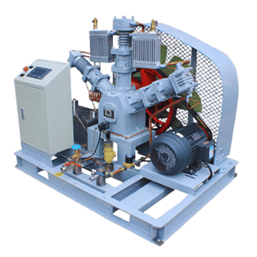
Are oxygen booster compressors worth it?
Typically, yes – above ~20 Nm/day steady demand. Below that, cylinder delivery frequently has the overall lowest cost because the booster’s capex plus electricity plus maintenance amortizes to a similar level less quickly; industry history through 2025 suggests on-site PSA + booster total operating expense in the $0.07-$0.11 [8] /m range (energy plus maintenance combined) vs cylinder delivery at $3-$15 [9] /m and bulk liquid oxygen at $0.15-$0.75 [10] /m once you are managing significant daily consumption levels sustaining the system-fed demand load.
A realistic break-even model
| Daily demand | Typical on-site vs cylinder outcome | Payback window |
|---|---|---|
| <10 Nm³/day | Cylinder delivery usually wins — on-site capex overwhelms operating savings | N/A (no break-even) |
| 20–40 Nm³/day | On-site break-even in most markets; strong supply-reliability benefit | Typically 2–4 years |
| 80+ Nm³/day | On-site dominates; in high-cylinder-cost or unreliable-delivery markets, payback can compress to 18 months | 12–24 months |
Two factors commonly distort the calculation:
- Electricity cost. Well-designed PSA systems operate at specific energy consumption under 0.4 kWh/m of oxygen. In a market with expensive electricity, that number is your biggest single opex line. Low-cost-power markets tip the math decisively toward on-site.
- Backup redundancy. Any serious on-site installation needs a standby cylinder rack for generator or booster downtime. This capex is often left out of naive ROI models. Include it.
Engineering Note – Why the “40-60% savings” Claim Needs a Denominator
Vendor pages sometimes cite “40-60% reduction in per-unit O cost” from switching to on-site generation. The figure is roughly accurate at the right demand profile – 20+ Nm/day of steady consumption in a typical electricity market. At 5 Nm/day intermittent or in a high-electricity market, the same switch may barely break even. Treat the 40-60% number as a ceiling for the best-fit case, not an automatic guarantee.
Broader market direction favors on-site installation: the global PSA oxygen generator market was roughly $3.96 billion in 2024, expected to grow to ~$4.62 billion in 2025 and reach ~$15.85 billion by 2033 at a 16.66% CAGR. That trend is not a marketing artifact; it reflects the real economics of owning versus subscribing to gas supply for any mid-to-high-volume industrial or healthcare operation.
To translate the model into a unit spec, see custom oxygen booster configurations for the 5–100 Nm³/h range the ROI calculation above assumes, or the broader air booster compressor comparison for non-oxygen parallel services.
Installation, Maintenance, and Common Failure Modes
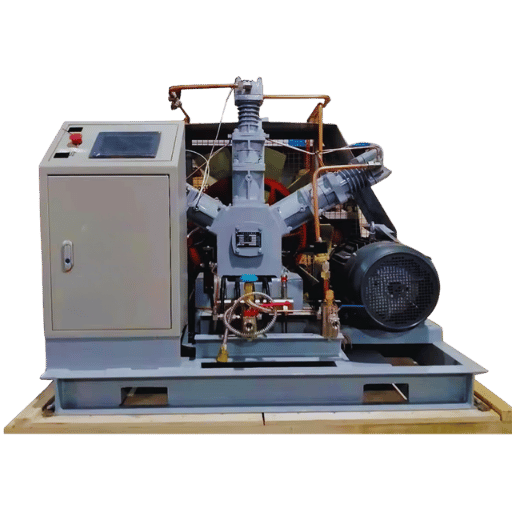
The parameters below are compiled from industry practice guides and practitioner experience in booster compressor forums. Your specific interval values will vary with ambient conditions, duty cycle, and gas-source cleanliness – treat these as starting points for a commissioning-based plan, not as universal numbers.
Maintenance interval starting points
| Component | Indicative interval | What to verify / replace |
|---|---|---|
| Inter-stage filter elements | Every 2,000 operating hours | Replace; inspect downstream valve faces for particle marks |
| Non-return inlet valve | Every 2,000 hours or on any flow anomaly | Seat condition, free movement; stuck valves are a documented continuous-duty failure mode |
| PTFE piston rings / packing | Every 4,000–8,000 hours | Ring wear, liner scoring; oxygen-clean before reinstall |
| Discharge valve plates | Every 4,000–8,000 hours | Seat integrity, chrome plating condition |
| Pressure relief valves | Annual functional test | Set-point verification per EIGA Doc 04/18 guidance |
Three failure modes that matter more than the spec sheet suggests
- Inter-stage valve fouling. Particle carryover from the generator, or moisture slip that did not get condensed, progressively reduces valve-seating integrity. Symptom is often a slow rise in stage-2 discharge temperature before any pressure anomaly. Practitioners on engineering forums note that non-return valves can stick fully closed in continuous duty; inspection interval matters more than nominal service hours.
- PTFE ring wear and liner scoring. Normal wear, but accelerated by moisture, oil-ingression from upstream (yes, it happens on new installations with poor commissioning), or inlet-filter degradation. Reduced volumetric efficiency is the visible symptom – the unit cannot hit its rated flow at the rated pressure.
- Inlet moisture excursion. PSA units can slip moisture under heavy duty or desiccant aging. A booster without inlet moisture measurement observed with wet oxygen will see valve and piston/cylinder corrosion weeks before a plant-wide indicator. Industry reports suggest the symptom shows up earlier in the form of daily-valvemotorimpulse-driven units showing premature corrosion – akin to compressor-wear, but originating upstream.
Common commissioning flaw: Fail to purge with dry nitrogen between assembling a unit and running it oxygen. Preventable failure mode that correlates strongly to early unit failures documented elsewhere in the industrial-gas fire literature.
Summary: For a boiler that was designed, built, assembled, and commissioned properly, operating on nominal inspection audit: a 15-year lifetime is de rigeur. When it doesn’t make it that long, early failures almost always link to contamination (baked-in or upstream) or deferred inspection rather than manufacturing flaws in system components.
Frequently Asked Questions
What is the difference between an oxygen booster compressor and an oxygen concentrator?
View Answer
An oxygen concentrator segregates ambient air to get the lowest-cost continuous source of oxygen on site, at a correspondingly low pressure (1-6 bar). An oxygen booster compresses the already-focussed oxygen up to 2-350 bar for storage or distribution. Used together, the two are nearly ubiquitous.
Can an oxygen booster compressor fill medical oxygen cylinders?
View Answer
Absolutely, provided it was designed for oxygen service and assembled on that basis with a valid oxygen generator integration. Medical oxygen cylinders are typically filled at 150 bar. Use a continuous oxygen analyzer alarm at >96% and <90%, in complete conformance to ISO standard specifications. US-only: unless otherwise specified, the lead-label on your Medical Oxygen Cylinder reads USP; a blank label indicates the “Oxygen Gas USP” standard of purity of 99%.
What safety precautions should be taken around oxygen compression equipment?
View Answer
Vehicles and computers sure do run on hydrocarbons, but plants and process equipment don’t – follow the specifications outlined on CGA G-4.1 during assembly and modifications. Separate identification and document each stage/level-over pressure interconnectedredundant relief device, so for each system we can verify operation and anti-tamper capability on the base unit, the system stage, and the link between them. Conduct an annual program check of each relief device and discharge temperature protector. Confirm the unit was flushed with nitrogen and dewatered at commissioning. Develop a listing of ISO-approved products and treat every oxygen-related fire accident as a possible root cause investigation into upstream contaminant-ingress.
What pressure range can an oxygen booster compressor achieve?
View Answer
Entry pressure 3-6 bar supplied from a PSA or VPSA generator; commonly-observed pressures are 150 bar (2 stage compressor) or 200 bar (4 stage); aerospace/industrial custom packages achieve 350 bar and can approach 1000 bar in diode style units.
Does an oxygen booster require a dedicated power source?
View Answer
Electric-driven units (typically in the 2-22 kW range) generally require industrial- or aerospace-grade three-phase power, efficiency-class IE3 or above. Air-driven boosters substitute compressed air for electricity; desirable where ignition hazards or ultra-portability are present; undesirable due to the limited continuous-duty flow rate. Assessment of starting motor load against plant power capacity is prudent in design planning.
What should you pay attention to when buying an oxygen booster?
View Answer
In addition to the usual flow and pressure spec, request four common documents: (1) ASTM G94 / G63 material selection logic covering the oxygen-wetted path (2) CGA G-4.1 cleanliness report for system commissioning, with measured non-volatile residue (3) stage-by-stage relief valve set-points, test records (4) the parts kit for overhaul, with recommended overhaul and maintenance intervals. Any vendor who can’t produce these is not offering a fully oxygen-qualified unit.
Ready to specify a unit for your application?
Run your numbers through the 5-Question Triage at the top of this page, then send in your flow, pressure, purity and duty-cycle targets to our engineering team – we’ll match them against a configuration and a budgetary quote, normally within 2 business-days.
About this guide
This article was assembled by the PG Compress engineering group with open industry data from ASTM, CGA, NFPA, EIGA, WHO/ISO, industrial gas fire investigations, and expert conversations on engineering forums. When numeric claims depend on operating conditions — payback period, maintenance window, per-m³ cost — a range is listed rather than a specific value. Confirm any quoted figure with your own site conditions and your supplier’s commissioning report prior to calculating budgets and specs.
References & Sources
- ASTM G94 — Standard Guide for Evaluating Metals for Oxygen Service — ASTM International
- CGA G-4.1-2018 — Cleaning Equipment for Oxygen Service (7th ed.) — Compressed Gas Association
- EIGA Doc 04/18 — Fire Hazards of Oxygen and Oxygen-Enriched Atmospheres — European Industrial Gases Association
- NFPA 53 — Recommended Practice on Materials, Equipment, and Systems Used in Oxygen-Enriched Atmospheres — National Fire Protection Association
- NASA TM-2007-213740 — Guide for Oxygen Compatibility Assessments on Oxygen Components and Systems — NASA Technical Reports Server
- Medicinal Oxygen Specification — World Health Organization / ISO 7396-1 cross-reference
Related Articles
- What is a booster compressor — definitional primer on shared properties between all gases
- How booster compressors operate — thermodynamics and stage-design considerations
- Booster compressor types — cross-technology comparison in depth
- Booster compressor selection guide — application-neutral selection walkthrough
- Industrial gas booster applications — welding, cutting, filling-station usage
![Low Pressure Hydrogen Compressor Applications [Guide]](https://pgcompress.com/wp-content/uploads/2026/09/low-pressure-hydrogen-compressor-applications-blog-featured-150x150.png)