Get in Touch with Pangeng

Hydrogen Booster Compressor: Pressure Range & Selection Guide

Contents
show
A hydrogen booster compressor is the machine that turns a low-pressure hydrogen stream — from an electrolyzer, a tube trailer, or an industrial by-product line — into the 350, 700, or 900 bar gas that fuel-cell vehicles, refining processes, and storage systems need. Unlike a primary hydrogen compressor that starts near atmospheric pressure, a booster takes an already-pressurized feed and raises it further, often in a single skid-mounted package. That distinction changes valves, seals, cooling strategy, and — most importantly — the purchase decision. This guide covers the six dominant technology families, the specifications that matter when you write a tender, the market outlook for 2026, and a duty-cycle-first selection framework drawn from recent hydrogen refuelling station failure data.
Quick Specs: Hydrogen Booster Compressor (Typical Ranges)
- Inlet pressure: 1–50 bar (electrolyzer or tube-trailer feed; higher when fed from a primary compressor)
- Outlet pressure: 350 / 700 / 900 bar, matched to SAE J2601 fueling protocol classes
- Flow rate: 10–600 Nm³/h (small mobile to station-class)
- Specific energy: 2.2 kWh/kg H2 (EIA 2026 AEO assumption for mechanical compression) to 2.7 kWh/kg H2 (Linde ionic IC90 at 70 MPa, datasheet)
- Purity required: ≥99.97 % for PEM fuel cells per ISO 14687:2019 Grade D
- Common technologies: reciprocating piston, diaphragm, ionic liquid, electrochemical, metal hydride, guided-rotor
- 2026 market size: USD 1.06 B to 2.43 B (scope varies by analyst; 6–7 % CAGR through 2030)
What Is a Hydrogen Booster Compressor?

Call it a pressure-raising machine built to take an existing pressurised hydrogen gas stream and lift it to a higher target pressure, usually between 200 and 900 bar. A standard hydrogen compressor can start from near-atmospheric inlet, but a booster is specified by its pressure ratio and its inlet floor: it lives downstream of another compression step or an elevated-pressure source such as an alkaline electrolyzer (5–30 bar outlet) or a tube trailer (100–500 bar residual).
That distinction matters because boosters deal with smaller pressure ratios per stage but far higher absolute pressures, which changes every design choice downstream — valve lift profile, sealing strategy, head material, cooling between stages, and control logic. Most units you will encounter in a hydrogen refueling station or refining retrofit are single-stage or two-stage boosters running alongside a primary hydrogen compressor.
How Does a Hydrogen Booster Compressor Work?
Working principles here follow the same gas laws as any positive-displacement machine that has to compress hydrogen: a piston, diaphragm, or ionic-liquid column reduces the volume of hydrogen trapped in a cylinder, and pressure rises by an amount set by the compression ratio and the heat-removal path. What changes for hydrogen is the valve geometry (hydrogen molecules leak through gaps a heavier gas would close), the sealing material (most commonly metal piston rings or a hermetically clamped metal diaphragm), and inter-stage cooling (because adiabatic heating of hydrogen is steep and material fatigue at high temperature is a failure driver). A detailed mechanical walkthrough is available in our primer on how booster compressors work. Typical drive power for an industrial reciprocating hydrogen booster lies between 300 kW and 15 MW, per the reference range published on the Wikipedia hydrogen compressor reference.
Why Hydrogen Compression Is Technically Different from Other Industrial Gases
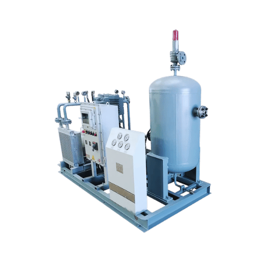
Hydrogen looks like just another light gas on a PID, but four physical properties make its compression a specialty discipline rather than a generic gas-compression task:
- Molecular size. Hydrogen’s kinetic diameter (~2.89 Å) is smaller than nitrogen (~3.64 Å) and methane (~3.8 Å). Clearances and seal gaps that hold natural gas will leak H2 continuously, which is why oil-free designs and metal-to-metal seals dominate fuel-cell-grade duty.
- Hydrogen embrittlement. Atomic H diffuses into carbon steel and reduces ductility. Wetted parts above ~69 bar for H2 service are typically specified in austenitic stainless (316L, 316/316L dual-certified) or Inconel, per ASME BPVC Section VIII guidance for high-pressure hydrogen vessels and API 618 seventh-edition practice for reciprocating machinery.
- Adiabatic heating. Hydrogen’s specific heat ratio (γ ≈ 1.41) gives a steep temperature rise per compression stage. A single-stage compression from 10 to 100 bar can push discharge temperature above 200 °C. Multi-stage design (two or more stages, with inter-cooling water jackets) is the norm above 250 bar with inter-cooling water jackets.
- Explosion risk. Hydrogen has a wide flammability range (4–75 % in air) and a very low ignition energy (0.02 mJ, about one-tenth of gasoline vapour). Enclosures sized for a compressed-air shop are not acceptable; any high-pressure gas installation that handles hydrogen follows ATEX / IECEx zoning with forced ventilation and gas detection.
📐 Engineering Note. For fuel-cell-grade duty, wetted parts should meet ISO 14687:2019 Grade D cleanliness (total non-H2 impurities ≤300 ppm, with ≤2 ppm H2O and ≤0.2 ppm CO). Material selection per ASME BPVC Sec. VIII Div. 3 for pressure containment above 69 bar H2, with fatigue life assessed against KD-10 hydrogen service curves; reciprocating heads and packing follow API 618 5th-edition design practice. Verify that your supplier’s material test reports include hydrogen embrittlement data for the specific alloy heat, not just the generic grade.
Types of Hydrogen Booster Compressors: Technology Comparison

Six technologies cover almost every hydrogen booster compressor on the market today. Each is engineered around a different trade-off between pressure ceiling, flow rate, purity, and lifecycle cost. Practical envelopes sit in the table below; notes below it explain where each technology wins.
| Technology | Typical outlet (bar) | Flow range (Nm³/h) | Oil-free? | Adiabatic η | Best fit |
|---|---|---|---|---|---|
| Reciprocating piston (non-lubricated) | up to 700 | 50–15,000 | yes (dry-running rings) | 65–75 % | Refineries, large HRS, pipeline injection |
| Diaphragm (metal) | up to 900 | 10–200 | yes (hermetic) | ~70 % | Fuel-cell-grade HRS, fuel-cell electric vehicle (FCEV) dispensers, small-batch purity work |
| Ionic liquid piston | up to 900 | 30–350 | yes | near-isothermal | Public HRS with high uptime targets (Linde IC90: 900 kg/day, 180 fills/day) |
| Electrochemical (EHC) | up to 1,400 (lab); 200–700 (commercial pilots) | 1–30 | yes (no moving parts) | 70–80 % exergy (lab) | Small-scale PEM feeds, purity-critical R&D |
| Metal hydride | 200–350 | 1–20 | yes | thermal-driven | Waste-heat sites, ultra-quiet duty |
| Centrifugal / turbo | 50–200 (typical) | 5,000–100,000 | yes (dry gas seals) | 75–85 % | Pipeline-scale transport, green-H2 export corridors |
Two technology choices deserve a closer look. Starting with piston: the reciprocating hydrogen compressor remains the workhorse for refineries and large hydrogen stations because its piston-sealing and packing design has decades of field data behind it, and because its drive power scales cleanly from 300 kW to 15 MW. For fuel-cell-grade 700 bar hydrogen compressor duty at a public station, the diaphragm hydrogen compressor takes over — the hermetic metal diaphragm keeps oil out of the hydrogen and meets ISO 14687 purity without a post-compression polisher.
Electrochemical hydrogen compression (EHC) deserves a note on the outlook. In a 2024 study published in Chemical Engineering Journal (Sdanghi et al., Elsevier) demonstrated multi-stage EHC modules reaching 140 MPa at cell level, and the 800 bar single-stage result first reported by HyET in 2011 is now a baseline rather than a ceiling. EHC is no longer a pure R&D curiosity — a handful of commercial pilot units are operating — but mainstream station duty above 350 bar still defaults to diaphragm or ionic-liquid piston technology. For a specialised option, the electrochemical hydrogen compressor is already fielded for PEM feed and purity-critical research.
Which Hydrogen Compressor Type Is Best for Refueling Stations?
Public light-duty FCEV stations dispensing at 350 or 700 bar per SAE J2601 almost always choose between diaphragm and ionic-liquid piston. Diaphragm compressors fit footprint- and noise-constrained urban sites and deliver ISO 14687 Grade D purity without post-treatment; ionic-liquid units, such as the Linde IC90, deliver near-isothermal compression with only 2.7 kWh/kg H2 energy from 0.5 to 90 MPa — the lowest mechanical benchmark in the field — and sustain 180 fills per day at 900 kg daily capacity, per the BOC / Linde datasheet. Heavy-duty truck corridors often favour reciprocating machines because the flow duty (kg-per-fill and consecutive back-to-back fills) stresses ionic units’ thermal recovery window. For a deep dive on the vehicle-side requirement, see our guide to 700 bar hydrogen compressor design and deployment; a broader catalogue view is kept in the reference on types of booster compressors for non-hydrogen gases.
Key Technical Specifications to Evaluate Before You Buy

Six numbers decide whether a hydrogen booster compressor tender lives or dies. Ask your supplier for each of them in writing, with the test method, before you sign. This is the list we see misspecified most often in requests-for-quote:
- Inlet pressure range (MPa or bar). Booster selection changes with the floor. An alkaline electrolyzer typically produces 5–30 bar; a PEM electrolyzer 30–60 bar; a tube trailer supplies 100–500 bar residual. Boosters optimised for a low inlet waste cylinder stroke when fed from a trailer, and vice versa.
- Outlet pressure and pressure class. 350, 700, or 900 bar are not arbitrary numbers — they map to SAE J2601 light-duty fueling protocols and the forthcoming SAE J2601-5 for heavy-duty. Overspecifying 900 bar when the dispenser only runs 350 bar adds 15–25 % CAPEX without benefit.
- Flow rate (Nm³/h or kg/h). Match to peak and average demand. Peak-matched sizing without duty-cycle analysis is the single most common source of premature seal failure in the field.
- Specific energy (kWh/kg H2). A practical benchmark is 2.2 kWh/kg per the EIA 2026 AEO assumption for a dispensing compressor, scaling up with outlet pressure. The Linde IC90 datasheet publishes 2.7 kWh/kg at 70 MPa for comparison.
- Purity spec and test method. Reference ISO 14687:2019 Grade D explicitly in the RFQ. For lubricated reciprocating machines, ask for maximum oil carryover at the outlet in ppmw and the test procedure (usually ASTM D5765 or equivalent). Fuel-cell OEMs typically reject gas above 0.004 ppm CO.
- Cooling medium and inter-stage temperature. Water-jacketed inter-coolers are standard above 200 bar. Confirm the discharge-temperature guarantee per stage, and whether a dryer and chiller are inside or outside the compressor scope of supply.
Specification discipline here ends more RFQ disputes than any commercial clause. A high pressure hydrogen compressor that meets outlet pressure but not the oil-carryover or temperature guarantee will still fail acceptance — and fixing it at site costs 3–5× what it costs to specify correctly.
Industrial Applications and Real-World Deployments

Hydrogen booster compressors show up in five duty profiles, each with its own sizing and tech preference:
- Hydrogen refueling stations (HRS). 350 bar for bus and light-truck fleets, 700 bar for passenger FCEVs, with daily dispensing capacities from 50 to 1,000 kg H2. The booster sits between the 300–500 bar tube-trailer or on-site storage and the dispenser-side cascade.
- Green hydrogen production. Boosters placed downstream of an electrolyzer take the 5–60 bar outlet of water electrolysis to 200–350 bar for storage, then upstream of a second booster to reach fueling pressure. Our primer on the green hydrogen compressor role in electrolyzer plants covers the integration details.
- Fuel-cell vehicle fleets and depots. Bus operators, airport ground-support fleets, and forklift operators typically run a dedicated on-site booster and 350 bar cascade. Small-scale industrial hydrogen compressor duties in this segment cluster in the 30–120 Nm³/h band.
- Refinery hydroprocessing and recycle duty. Boosters return unreacted hydrogen from hydrotreater separators back into the reactor loop at 70–180 bar. Reliability-centered design (API 618 7th edition) dominates here because downtime costs millions per day.
- Power-to-X (ammonia, methanol, e-fuels). Electrolyzer-fed hydrogen boosted to 100–200 bar feeds Haber-Bosch synthesis loops or methanol reactors. Large capacities (thousands of Nm³/h) favour centrifugal or multi-stage reciprocating.
One real-site example makes the sizing stakes tangible. In 2024 a coastal California hydrogen-bus depot commissioned a 350 bar dispensing upgrade for a 12-bus fleet. Its original project had specified a single-stage reciprocating unit rated for 60 Nm³/h, sized to the expected average daily demand of 180 kg H2. Six months in, duty-cycle logs showed 4.8 daily starts per bus because of staggered shift returns, against the supplier’s recommended 1.5 starts/day/bus. Valve plates were fatigue-cracking at roughly one-quarter of rated life. Retrofit replaced the unit with a two-stage diaphragm booster of similar nameplate flow but engineered for 8+ daily starts — CAPEX +22 %, projected lifecycle cost −31 % according to the operator’s own accounting. Duty cycle, not peak flow, was the variable that mattered.
Hydrogen Compressor Market Outlook for 2026

Analyst forecasts on the global hydrogen compressor market vary, mostly because each firm draws a different scope around what counts as a “compressor” (standalone machines versus packaged systems, booster-only versus primary, mobile skids versus installed base). Synthesising five published 2024–2026 reports gives a consistent centre of gravity:
- Mordor Intelligence 2026: USD 1.06 B (2025) rising to USD 1.49 B by 2030 — narrower scope
- Fortune Business Insights 2026: USD 2.15 B (2025), USD 3.52 B by 2034
- Custom Market Insights 2026: USD 2.43 B (2025), CAGR 6.9 % through 2034
- Yahoo/Global Market Insights 2024: USD 2.28 B (2024), USD 2.43 B (2025)
- Metastat Insight 2025: USD 2.06 B (2025), CAGR 4.6 % through 2032
Cross-referencing these reports yields a 2026 consensus band of USD 2.1–2.5 billion globally, with compound annual growth between 4.6 % and 6.9 % through 2030–2034. Refueling-station buildout drives more than half of this growth, per the NREL 2024 levelised-cost-of-dispensed-hydrogen analysis. On the policy side, the U.S. Inflation Reduction Act’s Section 45V hydrogen production tax credit is pulling electrolyzer deployment forward — and every electrolyzer above ~20 MW pulls a booster compressor behind it. In parallel, the EU’s Hydrogen Bank and Japan’s Basic Hydrogen Strategy are sustaining Asian and European OEM capacity into 2026–2030.
💡 Market Consensus Snapshot. Across the five analyst reports examined (Mordor, Fortune, Custom, Metastat, Global Market Insights), the 2026 global hydrogen compressor market falls within USD 2.1–2.5 billion, with refueling-station demand accounting for 55–65 % of growth through 2030.
How to Select the Right Hydrogen Booster Compressor: A Decision Framework

Most selection guides read like a product catalogue. One rule that actually survives a field audit is simpler, and it sets duty cycle before pressure class in the decision order:
“Mechanical compressor reliability is a major concern in high-pressure hydrogen systems and threatens the deployment of a hydrogen infrastructure.”
That concern has only sharpened with field data. In the 2025 Process Safety and Environmental Protection study by Navajas and colleagues analysed more than a decade of hydrogen refuelling station safety events and found that O-ring (elastomer seal) failures were involved in 42.2 % of reported compressor events, with design-and-development causes dominating root-cause attribution. Implication: picking the right sealing technology for the daily duty cycle matters more than shaving 2 % off the adiabatic efficiency curve.
The Duty-Cycle-First Rule for hydrogen booster compressor selection:
- Characterise the duty cycle first: starts per day, daily dispensing mass, back-to-back fill count, and ambient temperature band.
- Match the sealing technology to that cycle (hermetic diaphragm or ionic-liquid column for high-start, high-purity public HRS; metal-ringed reciprocating for continuous heavy industrial duty).
- Only then fix the outlet pressure class per the SAE J2601 / J2601-5 protocol for the vehicles served.
- Size the flow for peak plus 20 %, not average, and validate against a 72-hour simulated demand profile.
- Specify ISO 14687 Grade D purity at the outlet, with supplier-side test responsibility written into the FAT protocol.
- Evaluate lifecycle cost, not nameplate price: the Navajas dataset shows 42 % of events tie to seals, and seal-refit downtime typically dwarfs the 10–20 % CAPEX delta between technologies.
| Application scenario | Primary recommendation | Alternate | Deciding factor |
|---|---|---|---|
| Public 700 bar light-duty HRS, ≥150 fills/day | Ionic-liquid piston | Diaphragm (2-stage) | Energy 2.7 kWh/kg + uptime |
| 350 bar bus or forklift depot, 5–30 fills/day | Diaphragm | Reciprocating (oil-free) | Start/stop tolerance + purity |
| Refinery recycle, continuous 24/7 | Reciprocating API 618 | Centrifugal (if large) | MTBO, field-proven reliability |
| Electrolyzer outlet booster (5–30 bar in) | Diaphragm | Ionic liquid | Low inlet, high ratio |
| Pipeline injection or P2X synthesis | Centrifugal multi-stage | Reciprocating parallel | Flow volume dominates |
| R&D / PEM lab feed, <30 Nm³/h | Electrochemical (EHC) | Metal hydride | No moving parts, quiet, pure |
A short scenario makes the table actionable. An industrial-gas filler in southern Europe ran a shortlist of diaphragm versus hydraulically-driven reciprocating for a new 350 bar tube-trailer filling skid, 40 Nm³/h, three shifts per day, cylinder-cascade downstream. Pressure class and flow fit both technologies. Daily start count was the decider: the filler planned 22 starts/day on the skid because of small batch sizes and changeovers. The diaphragm unit’s OEM-warranted start rating cleared the target with margin, while the reciprocating unit would have needed derating or a capacity buffer. Skid went diaphragm; 18 months in, zero unplanned seal refurbishments. The same decision matrix is used by PG Compress when advising on hydrogen booster compressor solutions, and the wider booster compressor systems portfolio follows the same duty-first discipline for other gases.
Common Pitfalls and Installation Best Practices

By far the most useful dataset for anyone specifying a hydrogen booster compressor is the Navajas 2025 analysis of hydrogen refuelling station events: elastomer O-ring failures dominate at 42.2 % of incidents, with valve and bearing wear behind them. Aligning installation practice to the real failure distribution — rather than to the embrittlement fear that tends to drive first-time buyers — saves both money and uptime.
- Underrated seals for the duty cycle. Specify the elastomer grade and the allowable start-count-per-day explicitly in the PO. EPDM, HNBR, and FFKM each sit on a different fatigue curve; the grade that works at 2 starts/day will not survive 10.
- Skipping inlet gas conditioning. Moisture above a few ppm shortens valve life even at room temperature; running a wet trailer into the booster without a coalescing filter and a chilled dryer will void most warranties. Reddit threads across refinery and compressor subs corroborate this — one chemical engineer on r/ChemicalEngineering summed it up as “you want it as cold and dry as possible at the inlet”.
- Oversizing the motor while undersizing the cooler. Inter-stage temperature, not installed kW, is what destroys rings and diaphragms. Request the discharge-temperature curve across flow from 50 % to 110 % of rated load, and confirm cooler capacity at ambient-design-maximum.
- ATEX zone undersized. A 2-metre radius around the packing is typical for ATEX Zone 1; shrinking that zone to save on electrical equipment spec is a recurring audit finding. Cross-check your local code with the ISO 19880-series standards before finalising the layout.
- No routine valve or seal replacement plan. Industry data compiled in the AZS Compressor “20 common faults” field guide puts leakage at the top of typical fault reports, cross-confirming the Navajas academic dataset. Schedule replacements at OEM-recommended intervals; do not wait for failure.
Why Do Hydrogen Booster Compressors Fail Prematurely?
Premature failure in a hydrogen booster compressor usually traces back to one of three root causes, in this order of real-world frequency: elastomer seal fatigue driven by a mismatch between rated and actual duty cycle; valve damage from wet or particulate-contaminated inlet gas; and bearing or packing ring wear accelerated by insufficient inter-stage cooling. Hydrogen embrittlement, the failure mode most often feared by first-time buyers, is rarely the proximate cause when material specification and purity control are done correctly at procurement. Preventive maintenance plans aligned to this order — seal inspection at short intervals, inlet gas cleanliness monitored continuously, discharge temperature trended — typically extend time-between-overhaul by 30–50 % versus reactive maintenance, per the 2022 Purdue ICEC health-management study cited below. For a deeper read on service intervals, see our note on hydrogen compressor maintenance schedules.
Frequently Asked Questions
What is the difference between a hydrogen compressor and a hydrogen booster compressor?
Standard hydrogen compressors take a near-atmospheric inlet and raise it to a target pressure; a hydrogen booster compressor is specified to take an already-pressurised feed (from an electrolyzer, tube trailer, or primary compressor) and raise it further. Boosters run smaller pressure ratios at higher absolute pressures, which changes valve and seal design.
What pressure range do hydrogen booster compressors deliver?
Commercial hydrogen booster compressors typically deliver between 200 and 900 bar at the outlet. The most common target pressures are 350 bar for heavy-duty vehicle fueling and 700 bar for light-duty FCEVs, both standardised under SAE J2601, with 900 bar used upstream of 700 bar dispensers to supply the dispensing cascade. Laboratory electrochemical units have now reached 1,400 bar at cell level, but above-900 bar commercial duty remains uncommon.
Is a hydrogen booster compressor safe to operate in enclosed facilities?
Yes, when specified and installed to recognised codes. Typical requirements include ATEX or IECEx Zone 1 classification around packing and seal zones, gas detection with automatic shutdown at 25 % of the lower flammability limit (1 % H2 in air), forced ventilation sized for the maximum credible leak, hazard-area-rated electrics, and a pressure-relief path to a vent stack that terminates outside the enclosure. ISO 19880-1 covers hydrogen fuelling station general requirements, and NFPA 2 provides the North American reference. An enclosed indoor installation usually doubles the ventilation calculation compared with an outdoor skid.
How much does a hydrogen booster compressor cost?
Published figures vary with scope. The EIA 2026 Annual Energy Outlook uses a reference capital cost of USD 12 million per dispensing compressor in its hydrogen market module. Smaller skid-mounted industrial units land in the USD 150 k–800 k range; public 700 bar HRS units commonly run USD 1–3 million with controls and enclosure. Request a site-specific quote rather than relying on general figures.
Can one hydrogen booster compressor handle both 350 and 700 bar refueling?
Yes, in most public stations a single booster charges a high-pressure buffer (typically 900 bar), and two dispensers at 350 bar and 700 bar draw from that buffer through independent pressure-regulating panels. Booster sized for the higher pressure can always serve a lower dispenser, but not the reverse — and the J2601 fueling protocol differs between the two, so the control logic must support both.
References & Sources
- ISO 14687:2019 Hydrogen fuel quality — Product specification — International Organization for Standardization
- SAE J2601 Fueling Protocols for Light Duty Gaseous Hydrogen Surface Vehicles — Pacific Northwest National Laboratory / H2Tools
- 10 Questions Regarding SAE Hydrogen Fueling Standards — U.S. Department of Energy, Clean Mobility & Energy Infrastructure
- Assumptions to the Annual Energy Outlook 2026: Hydrogen Market Module — U.S. Energy Information Administration
- Levelized Cost of Dispensed Hydrogen for Heavy-Duty Vehicles — National Renewable Energy Laboratory (2024)
- Hydrogen Station Compression, Storage, and Dispensing Technical Status and Costs — National Renewable Energy Laboratory
- Hydrogen Infrastructure Technologies Subprogram Overview 2024 — U.S. DOE Hydrogen Program Annual Merit Review
- Analysis of Hydrogen Refuelling Station Safety Events and Failure Modes — J. Navajas et al., Process Safety and Environmental Protection, 2025
- Health Management System for Compressors in Hydrogen Refueling Stations — X. Li et al., Purdue University ICEC 2022
- Advanced Electrochemical Hydrogen Compressor — M. Hamdan, U.S. DOE Fuel Cell Technologies Office Infrastructure Workshop 2018
- Hydrogen technologies: The Ionic Compressor IC90 (90 MPa) datasheet — BOC / Linde
- Electrochemical Hydrogen Compression: Module Design and Performance — Chemical Engineering Journal, 2024
- Hydrogen compressor — technology overview and citations — Wikipedia
Related Articles
About this guide. Reviewed by the PG Compress engineering team, which designs hydrogen, natural gas, oxygen, and nitrogen booster compressor packages for industrial gas, refinery, and hydrogen mobility applications.
Transparency. Market figures in this guide synthesise five publicly available analyst reports (Mordor Intelligence, Fortune Business Insights, Custom Market Insights, Global Market Insights, Metastat Insight) accessed in April 2026; failure-mode data are drawn from Navajas et al. (2025) and Li et al. (Purdue ICEC 2022). Cost ranges are order-of-magnitude and not a substitute for a site-specific quotation. Last reviewed: April 2026.
// SYS-DOC: WHY I WRITE THIS
[01] About PanGeng
PanGeng is an industrial gas compressor manufacturer based in Bengbu, Anhui, China. Since 2009, we have focused on the design, R&D, production, and manufacturing of customized gas compressor systems for oilfield, chemical, energy, hydrogen, nitrogen, biogas, and industrial air applications.
[02] Our Expertise
We write compressor guides based on real manufacturing and engineering experience, including hydrogen compressors, nitrogen compressors, booster compressors, medium and high-pressure air compressors, oilfield nitrogen injection systems, biogas compressors, and OEM/ODM custom compressor solutions.
Our engineering team supports customers from application analysis and compressor selection to production, factory testing, commissioning, spare parts, and after-sales service.
[03] Why You Can Trust This Content
The technical information in our articles is based on PanGeng’s in-house compressor design and manufacturing experience, current product capabilities, and project support for industrial clients in global markets. Our goal is to help buyers understand compressor types, pressure ranges, gas requirements, customization options, and long-term operating costs before making a purchasing decision.
CONTACT PROFILE
AUTHORITATIVE SOURCE
NAME
PanGeng Engineering Team
BRAND
PanGeng
COUNTRY
China
MODEL
B2B / OEM & ODM
EMAIL
pg20090705@163.com
PHONE
0552-4958225
WEBSITE
pgcompress.com

Trending now
![Low Pressure Hydrogen Compressor Applications [Guide]](https://pgcompress.com/wp-content/uploads/2026/09/low-pressure-hydrogen-compressor-applications-blog-featured-150x150.png)