Get in Touch with Pangeng

How to Size Feed Air for a Nitrogen Generator

Contents
show
Calculation and commissioning guide
N2 feed air compressor sizing begins with the nitrogen duty, not a compressor catalog. Transform the required product flow through the generator vendor’s air factor, normalize the flow basis, take into account real delivery loss, and prove it at peak demand.
This guide performs those calculations and verification tasks. It doesn’t compare product families or serve as a surrogate to an engineered quote. For commercial configurations and packages, use the separate nitrogen compressor systems page.
This compressor sizing guide is for industrial facilities that generate nitrogen on site. It helps you size the compressor properly from process duty, rather than applying advice for home use or general air tools, where a general guide tells readers to identify your tools or machinery before they size compressor capacity. The correct size is the one that meets defined pressure and flow conditions with traceable evidence.
The sizing rule: select on delivered free air at the generator inlet, at the required pressure and site condition. Displacement, motor power, or an unlabeled cubic-feet-per-minute value is not a complete capacity basis.
Start With the Air-to-Nitrogen Conversion Chain
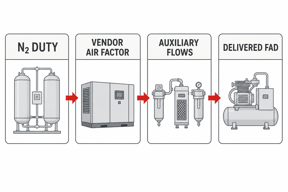
A nitrogen generator rejects part of the incoming air while concentrating nitrogen. Feed-air demand is then greater than product nitrogen flow. The governing input is a duty-specific air factor from the generator vendor, stated for the required purity, product pressure, inlet condition and technology.
A documented PSA nitrogen process illustrates why the conversion is a cyclic system duty rather than a one-to-one air-to-product-flow assumption.
Base feed-air flow = design N2 flow × vendor air factor
Keep auxiliary consumption outside that multiplication. Dryer purge, drains, control air, leakage, and other users have different causes and may not scale directly with nitrogen output. Showing them as separate rows makes the calculation auditable, keeps preventive maintenance allowances visible, and prevents a hidden margin from being counted twice.
Duty
Define minimum, normal, and peak nitrogen flow, event duration, product pressure, and the composition meant by “purity.”
Conversion
Obtain the generator’s feed-air consumption at that exact duty and note its reference temperature, pressure, and moisture basis.
Delivery
Correct for site conditions and add documented auxiliary flows while preserving the generator’s minimum inlet pressure.
Calculate Required Compressor FAD Step by Step
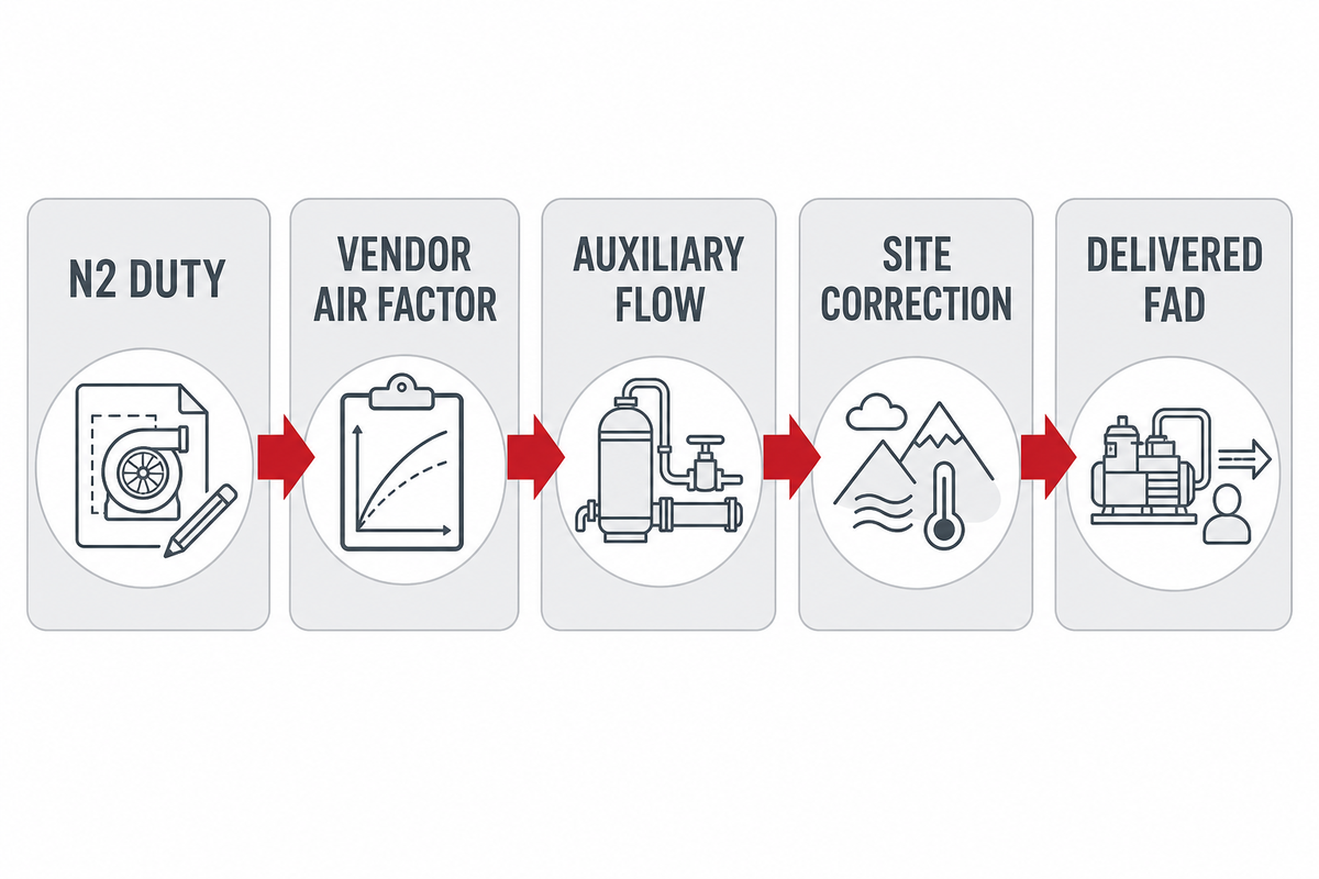
Free Air Delivery, or FAD, is the amount of air at standard conditions that the compressor can actually deliver. Always confirm whether a proposal reports FAD, actual inlet volume, standard flow, or theoretical displacement; the same number can represent different mass flows when its basis changes.
A flow rate may be measured in cubic feet per minute, cubic meters per hour, or liters per second. Record whether psi means pounds per square inch gauge or absolute, and never compare values until the reference basis is the same. The nitrogen gas compressor sizing guide addresses the downstream gas compression calculation, if it occurs after the generation point.
Your compressed air needs must be expressed at one reference condition. Higher CFM on a mismatched basis doesn’t prove higher usable capacity, and distinct psi needs belong in the pressure ledger. This guide will help you understand airflow as mass delivery rather than a catalog item.
How do I calculate compressor CFM for a PSA nitrogen generator?
First calculate the base feed air from peak nitrogen duty, and the air factor provided by the PSA vendor. Add any documented auxiliary flows, then consider only the site correction and the operating reserve identified by the compressor vendor, for the FAD rating in question. Finally, verify that the selected machine delivers this flow at the minimum required generator-inlet pressure after treatment and piping losses.
The required flow depends on the generator duty, while the volume of air the compressor can deliver depends on its rating conditions. A compressor that can handle the nominal calculation may still be the wrong compressor selection if site derating or treatment loss is omitted. The nitrogen compressor specifications guide should be consulted when capturing wider package data.
- Freeze the nitrogen duty. Capture the peak simultaneous N2 flow, purity definition, product pressure, demand duration and allowable interruption.
- Normalize units and compare bids. In the case of N2 and Feed-Air, find a common reference basis. When converting Nm³/h to cubic feet per minute, provide the absolute temperature and pressure of the system.
- Use the vendor air factor. Use the value pertaining to the particular generator model and duty point in question.
- Explicitly add known auxiliary flows like dryer purge and control air, drains and leakage as auxiliary flow rows.
- Use site correction. Ask the compressor supplier to correct capacity for altitude, ambient temperature, inlet restriction, cooling condition, and its rating basis.
- The compressor must supply the calculated air flow while ensuring the generator’s minimum inlet pressure is maintained across the real treatment train.
- Test resilience separately. Size short-event storage, growth allowance, and duty/standby availability from their own policies rather than hiding them in one multiplier.
Illustrative method, not a vendor selection: suppose a plant needs 100 Nm³/h of N2 and the chosen generator’s documented air factor at that duty is 3.2. Base air is 320 Nm³/h. If documented auxiliary demand is 20 Nm³/h, the worksheet carries 340 Nm³/h before supplier-specific site correction and resilience decisions. A different purity, generator, or reference basis can change the result.
| Worksheet field | Illustrative entry | Who must replace or confirm it |
|---|---|---|
| Peak product flow | 100 Nm³/h N2 | Buyer |
| Product specification | 99.9% stated composition basis | Buyer and generator vendor |
| Vendor air factor | 3.2 Nm³ air per Nm³ N2 | Generator vendor |
| Calculated base air | 320 Nm³/h | Worksheet calculation |
| Auxiliary demand | 20 Nm³/h | Treatment suppliers |
| Pre-correction duty | 340 Nm³/h | Worksheet calculation |
| Minimum generator inlet | 7.0 bar(g) | Generator vendor |
| Illustrative ambient | 35°C | Buyer |
| Illustrative elevation | 500 m | Buyer |
| Peak-event duration | 10 min | Buyer operating record |
| Receiver pressure band | 7.5 to 6.5 bar(g) | System designer |
| Motor and power check | kW at the stated duty | Compressor supplier |
All numbers in this example are for illustration only. Don’t use them in a real case. Replace them with signed duty data and supplier calculations.
Do Not Reuse One Air Factor Across PSA and Membrane Systems
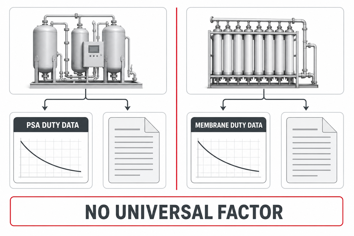
Pressure swing adsorption and membrane generation air separation use different mechanisms and technologies. Recovery behavior depends on purity, pressure, temperature, and control sequence of the equipment as well as design. One air factor cannot safely represent every nitrogen generation system.
The control and storage interactions described in this PSA nitrogen-generation record reinforce the need to use the selected system’s duty-point data instead of transferring one ratio across technologies.
How does feed-air demand change between PSA and membrane nitrogen generators?
Behavior is dependent on each vendor’s performance curve at the required purity and conditions. A higher stated purity often reduces recovery, but that observation is not a universal sizing equation. Compare air consumption, product flow, basis, inlet pressure and temperature of the feed air stream.
| Input | PSA check | Membrane check | Buyer action |
|---|---|---|---|
| Purity definition | Confirm whether the guarantee states residual oxygen, N2 plus argon, or another composition | Confirm oxygen content and the stated product basis | Do not treat every “99.x% N2” label as equivalent |
| Air factor | Use the model’s cycle and duty-point data | Use the selected membrane bundle’s curve | Request a signed value at the required duty |
| Operating range | Check cycling, bed equalization, low-load behavior, and receiver configuration | Check pressure, temperature, turndown, and product vent behavior | Evaluate minimum, normal, and peak cases |
| Final hold point | Vendor performance data controls the compressor calculation | Label a rule-of-thumb result preliminary | |
Add Real System Losses Without Double-Counting Margin
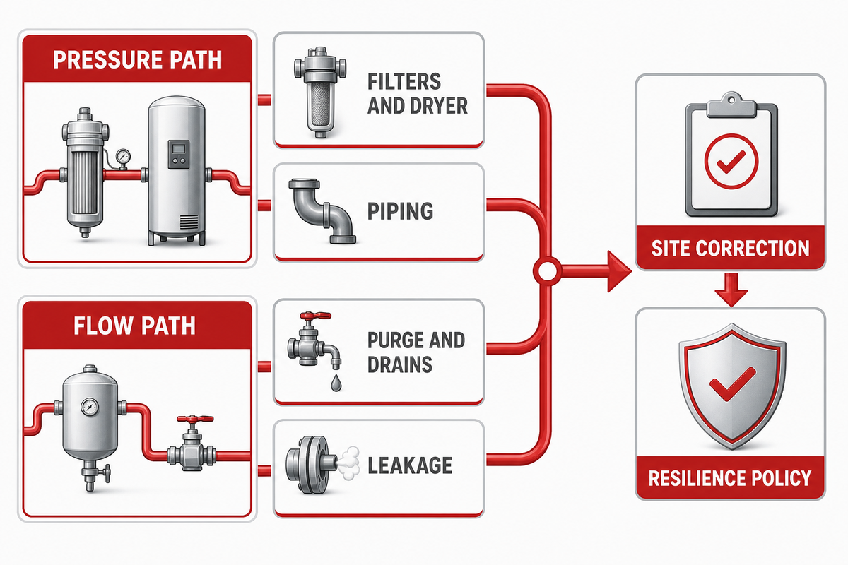
The air system loses pressure and flow in many ways. Filter and dryer pressure drops reduce the pressure available to the generator. Purge, leakage and drains cause loss of flow. Altitude and temperature can reduce compressor output. A future-growth allowance is a business decision. Lumping all these together in one percentage conceals both cause and effect.
The U.S. Department of Energy’s compressed-air sourcebook treats demand, pressure drop, storage, controls, and performance measurement as separate system considerations.
| Loss category | Pressure or flow? | Evidence | How it affects selection |
|---|---|---|---|
| Aftercooler, filters, dryer, piping | Pressure | Clean and design-change pressure drops at rated flow | Raises required compressor discharge pressure |
| Dryer purge, drains, control air | Flow | Manufacturer consumption at the selected cycle | Adds to required FAD |
| Plant leakage | Flow | Measured air audit or bounded project allowance | Adds only if this compressor supplies the leaking network |
| Ambient and altitude | Capacity correction | Compressor supplier rating correction | Changes delivered capacity and possibly power |
| Growth or standby policy | Resilience | Buyer-approved scenario | Changes installed capacity or redundancy |
| Oil-free or lubricated architecture | Air-quality boundary | Supplier statement and treatment specification | Changes contamination control, not the flow equation by itself |
| Minimum generator inlet | Pressure | Generator performance data in bar(g) or psi(g) | Sets the lowest acceptable pressure after losses |
| Peak duration | Time | Demand record in seconds or minutes | Separates continuous flow from a storage event |
| Receiver recovery | Flow and time | Pressure band in bar or psi and refill time in minutes | Confirms the next peak can be served |
Build one pressure ledger from the compressor outlet to the generator inlet and a flow ledger from the consumer back to the compressor and compare both at the same operating case. A 10 psi increase doesn’t automatically replace the lost flow and increased pressure can waste energy and move equipment beyond its operating limits.
Select Compressor Type, Control Band, and Receiver Strategy
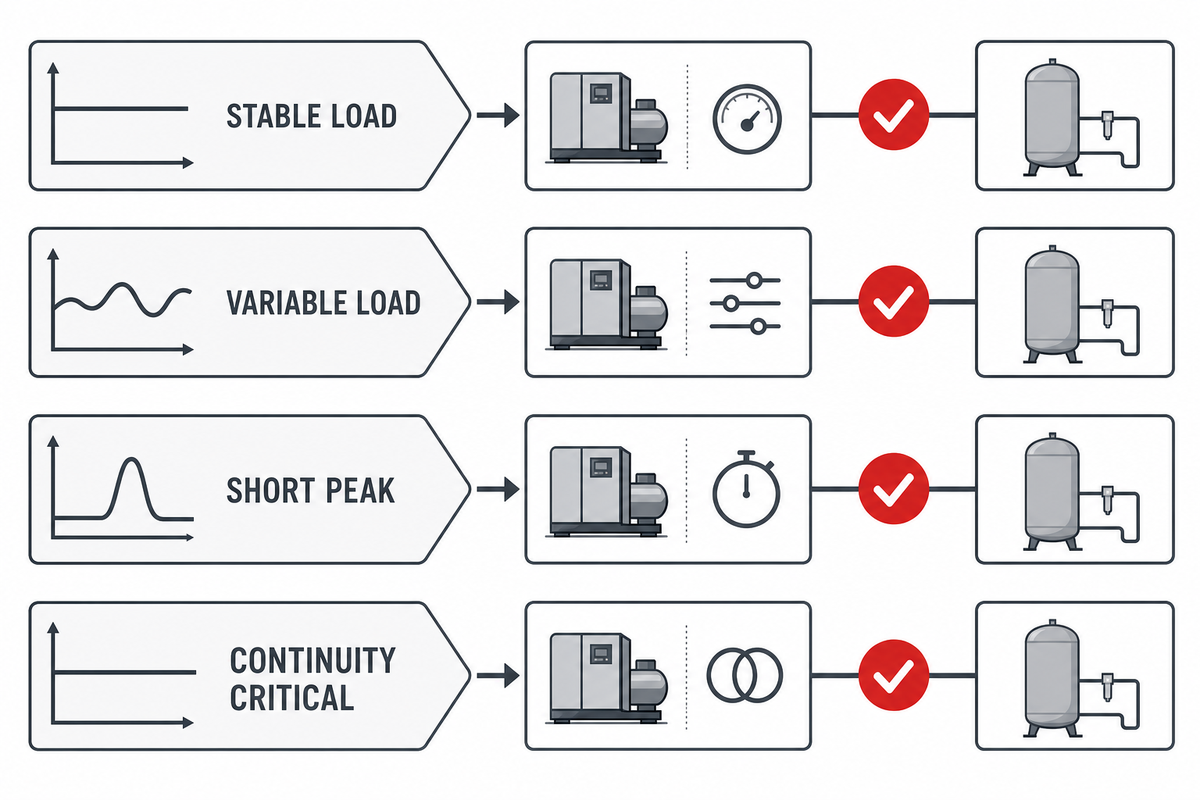
The right compressor is based on the maximum demand. A screw compressor may be continuous for industrial duty while fixed-speed or variable-speed drives may be appropriate for different conditions. Review energy efficiency across the actual profile including the minimum-load case.
The compressor’s control range must let the plant complete each demand task within an acceptable time. If storage meets the demand and recovery is before the next cycle, within an acceptable time frame, there should be no restriction at the generator inlet, relatively low pressure, even if the compressor is producing higher CFM at its outlet.
There’s no right air compressor size for every case. Make a list of the requirements for your facility, then ask whether the compressor can deliver steady airflow at peak demand and remain stable at low load. An explanation of a rating by a compressed air sales professional is possible, but the conversion duty has to be confirmed by the generator vendor.
| Demand pattern | Control question | Receiver role | Risk to check |
|---|---|---|---|
| Stable continuous load | Can the machine stay near an efficient operating point? | Buffers control movement and short disturbances | Excessive unloaded run time |
| Wide but sustained variation | Does turndown match minimum and normal demand? | Smooths transitions | Low-load cycling or inefficient control |
| Short repeatable peak | Can storage cover the event within an acceptable pressure swing? | Supplies temporary flow and must recover before the next event | Using storage to disguise inadequate continuous capacity |
| Interruption is unacceptable | Is duty/standby or staged capacity required? | Supports transition, not full redundancy | Counting a spare machine as flow margin twice |
The compressed-air receiver is separate from the product receiver and are on opposite sides of the generator. If the product receiver changes, re-check the air factor with the generator vendor, because some PSA sequences can use stored product gas during regeneration.
Refilling the tank is a timed recovery duty, not proof of continuous capacity. Likewise, an oil-free label or a lubricated compressor description addresses architecture and air treatment. It doesn’t address delivered flow. For that boundary, see the focused oil-free versus oil-lubricated nitrogen compressor comparison.
Send Suppliers a Complete Duty-Point Worksheet
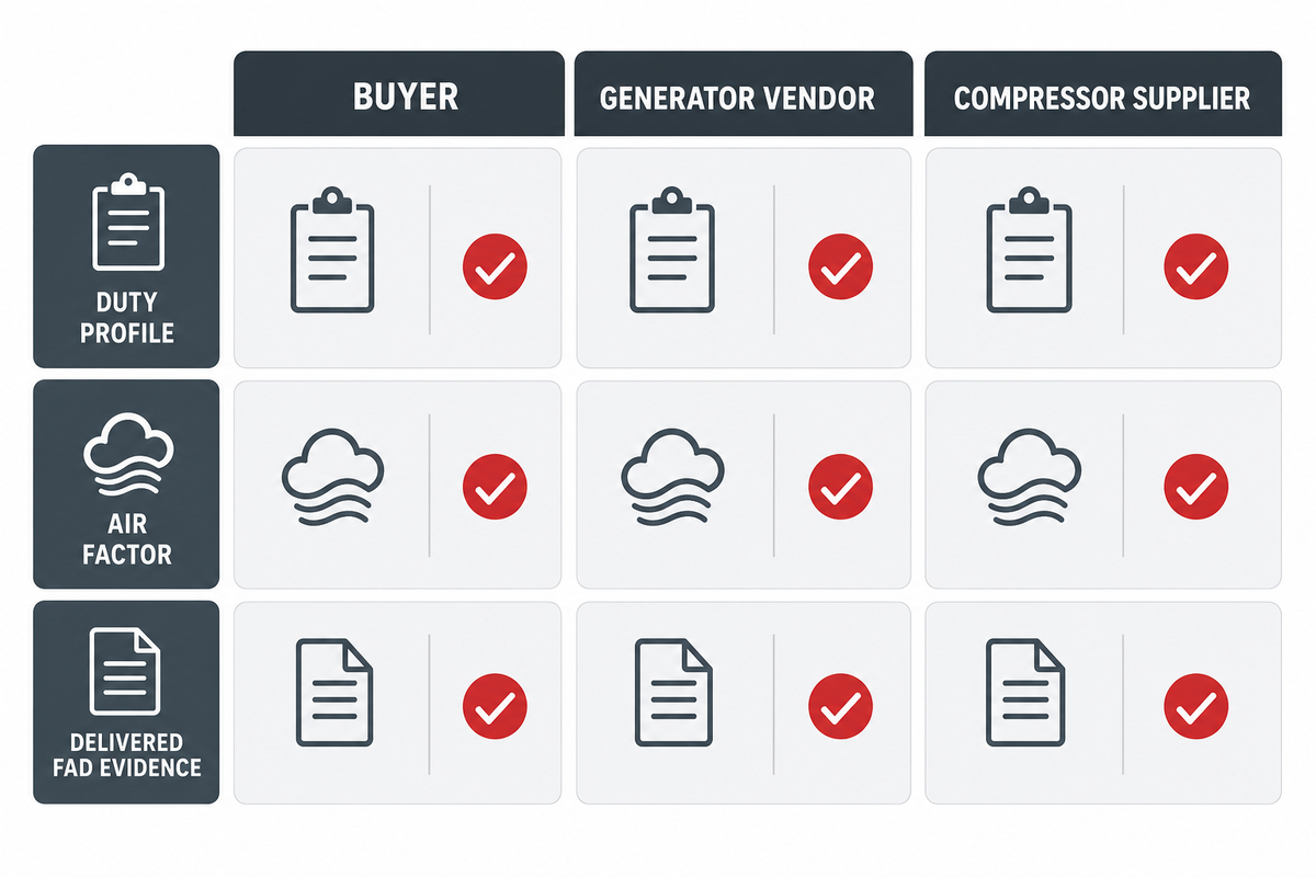
An explanation for the behavior of the generator is beyond nominal flow and purity. The worksheet needs to identify who owns the information and who verifies it. This keeps the compressor supplier from guessing generator behavior and keeps the generator vendor from assuming unlimited air supply.
What duty-point data should I send a compressor supplier?
Send minimum, normal, and peak N2 flow; the purity definition; product and generator-inlet pressure; demand duration; generator air factor and reference conditions; air-quality requirement; treatment equipment; ambient and altitude range; electrical and cooling utilities; allowable pressure band; reserve policy; receiver data; and the required commissioning evidence.
The amount of pressure alone is not the primary selection criterion. State the flow basis, whether demand is continuous flow or intermittent, and how long each event lasts. Also distinguish a feed-air compressor from a downstream booster using the nitrogen booster versus nitrogen compressor guide.
| Party | Inputs to own | Confirmation to return |
|---|---|---|
| Buyer or system integrator | N2 demand profile, site conditions, utilities, availability policy, growth case, acceptance boundary | Approved duty sheet and interface owners |
| Generator vendor | Air factor, purity definition, minimum inlet pressure, air quality, cycle behavior, product-receiver assumptions | Performance data for minimum, normal, and peak cases |
| Compressor supplier | FAD basis, site correction, operating map, power, controls, treatment losses, allowable ambient | Delivered flow and pressure at the defined battery limit |
Verify the Size With a Peak-Demand Commissioning Test
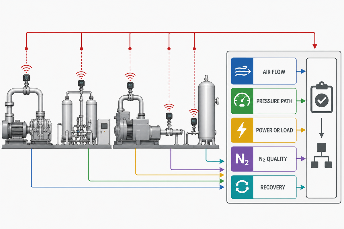
Reproducing a defined peak event during commissioning allows the system to be measured as a chain. A pressure dip alone does not prove the compressor is undersized. The cause could be a clogged filter, restricted test fixture, incorrect control band, slow valve, receiver problem, dryer behavior, or generator-cycle interaction.
The U.S. Department of Energy’s compressed-air evaluation guide likewise centers assessment on measured flow, pressure, power, and demand profiles.
How can I tell whether the compressor is undersized during peak nitrogen demand?
Measure delivered air flow, compressor discharge pressure, generator inlet pressure, treatment pressure drop, receiver pressure swing, compressor load or speed duty, N2 flow, oxygen concentration, and recovery time during repeated peak cycles. A capacity shortfall is valid when the compressor is operating at its allowable maximum and documented losses and the measurement system can’t account for the difference.
- State the N2 load, the duration, starting receiver pressure, and equipment operating conditions and acceptance limits.
- Check instrument calibration, range, sampling rate, and sensor response. Verify that temporary hoses, meters, or valves don’t restrict the flow being diagnosed.
- Run the peak. Record synchronized pressure, flow, power or load, valve state, N2 flow, and oxygen concentration.
- Repeat the cycle. Validate air receiver recovery and compressor cycling for the presence of control instability or a lack thereof, for a sufficient number of events to represent control behavior.
- Stable product. Assess nitrogen purity and generator cycling under the agreed procedure; don’t adopt a universal stabilization time from another installation.
- Fault Assignment. Differentiate compressor capacity shortage from pressure loss, treatment consumption, storage, controls, generator performance and measurement errors.
Use the 4-Layer Delivered-Air Check Before Purchase
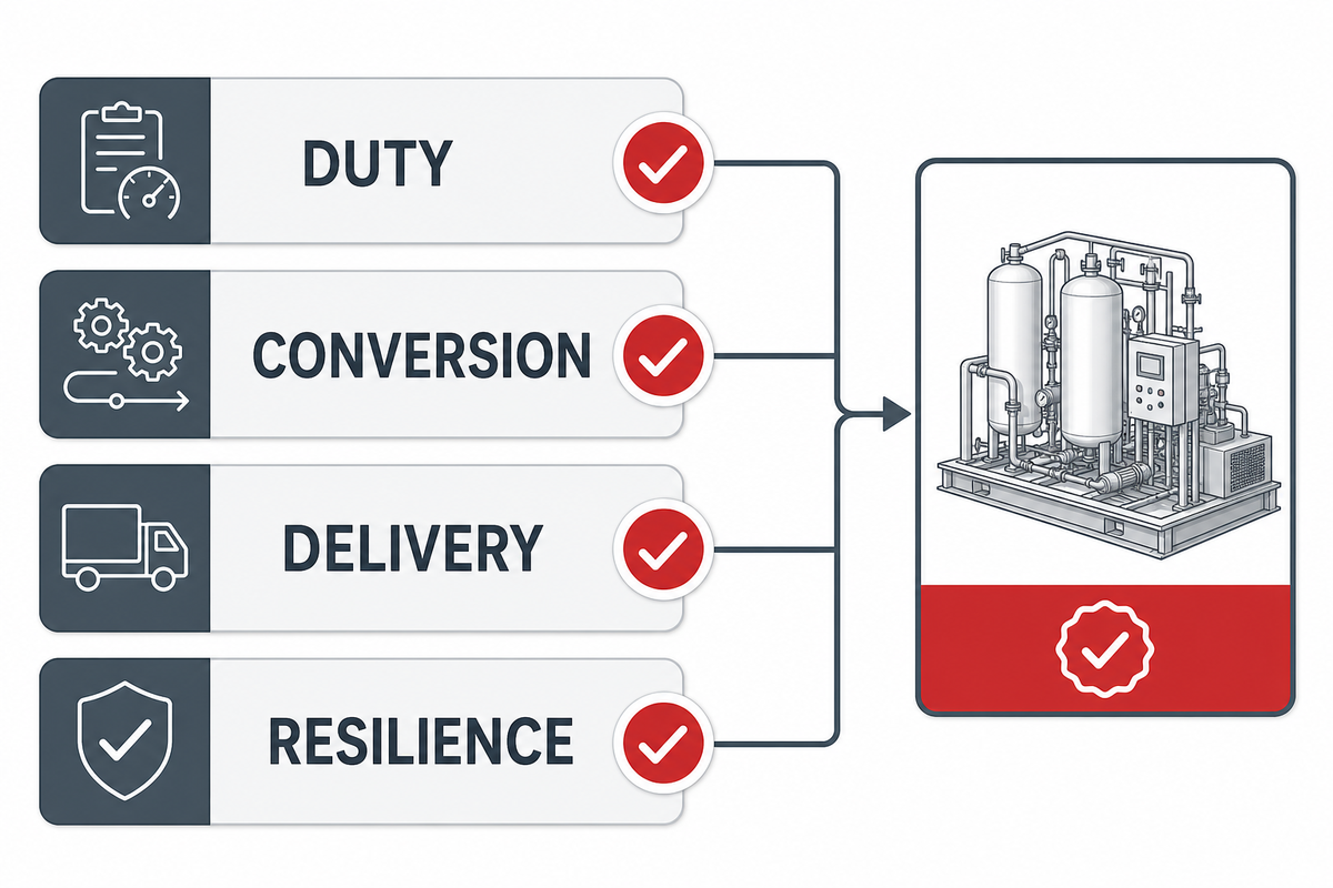
The 4-Layer Delivered-Air Check is a four-part decision framework that prevents a misleading nameplate comparison. It integrates duty, conversion, delivered capacity and resilience within a single review. Only approve the package when all four parts of the review are successful and each part has a record that’s testable and owned.
For the delivery and resilience layers, the U.S. Department of Energy’s system sourcebook provides the independent basis for reviewing pressure drop, storage, controls, and measured system performance.
1. Duty
If the peak N2 demand, purity, pressure, duration, or availability requirement is undefined, stop and complete the duty sheet.
2. Conversion
If the air factor isn’t tied to the generator and duty point, treat the result as preliminary.
3. Delivery
If reference conditions, site correction, losses, or inlet pressure are missing, the quoted air compressor capacity isn’t comparable.
4. Resilience
If peak storage, recovery, low-load control, maintenance, and standby policy are untested, capacity alone doesn’t prove continuity.
Current Sizing Direction: Verify Duty Data, Not Market Hype
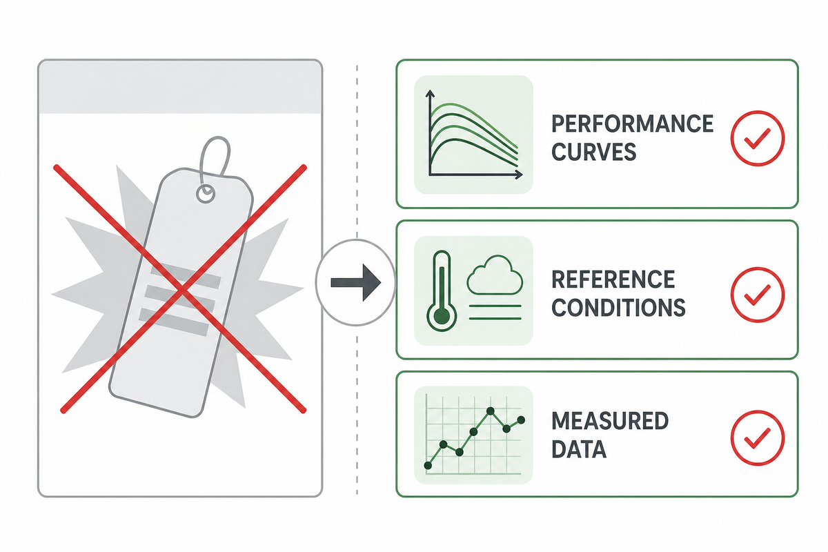
Reliable information on historical keyword usage wasn’t found. Therefore, no market-growth claims should inform engineering calculations. The recommended industry practice is less complex. Provide performance curves, define reference conditions, and measure pressure and flow and commissioning evidence relevant to the actual operating duty.
This evidence-first direction is consistent with the U.S. Department of Energy’s evaluation guidance, which relies on measured operating data rather than promotional capacity labels.
An improved air audit can better the input quality when an existing plant network feeds the generator. For a new standalone system, create the same discipline through explicit supplier data and an acceptance test rather than inventing a leakage or diversity value.
Frequently Asked Questions
What is the basic N2 feed air compressor sizing formula?
Multiply design nitrogen flow by the generator vendor’s air factor at the required purity and conditions, then add separately documented auxiliary air. Select the compressor by delivered FAD at the required pressure and site condition, not by displacement or motor size. Because purity and generator design affect recovery, the air factor must come from the duty-specific performance data.
Should compressor capacity be based on average or peak nitrogen demand?
Use the peak simultaneous demand that the system must sustain. A receiver may cover a short event when allowable pressure swing and refill time are calculated, but it doesn’t replace continuous capacity. Average demand is valuable for energy and control selection; using it alone can undersize the package when production peaks, purge events, or generator cycles overlap.
How much spare compressor capacity should a nitrogen generator have?
There’s no universal spare percentage. Separate known losses, credible growth, and availability policy. A duty/standby requirement differs from a flow margin, and adding both blindly can oversize the system. Document reserve against peak duration, receiver behavior, maintenance strategy, and the consequence of interrupted nitrogen before choosing installed capacity. Keep each allowance visible in the worksheet.
Does a higher delivery pressure reduce the required CFM?
No simple trade is safe. Higher pressure changes compressor power, generator performance, pressure loss, and the relationship between actual and standard flow. Compare every value on the same reference basis and select for the minimum generator-inlet pressure after real system losses.
Can the same air factor be used for 99% and 99.999% nitrogen?
No. Purity changes recovery and product flow, and the curve differs among PSA and membrane designs. Request feed-air consumption at the exact composition specification, inlet pressure, temperature, and reference condition. If only a broad ratio is available, mark the calculation preliminary and keep a verification hold point before compressor purchase.
What measurements are needed during commissioning?
Record delivered flow, compressor discharge and generator inlet pressures, treatment pressure drop, receiver swing, compressor load or speed duty, N2 flow, oxygen concentration, and recovery time during a defined peak event. Check instrument response and temporary restrictions so the combined record can distinguish capacity shortage from treatment, piping, storage, control, or measurement faults.
References & Sources
- (U.S. Department of Energy, Compressed Air System Evaluation)
- (U.S. Department of Energy, Improving Compressed Air System Performance)
- ISO 1217, Displacement compressors acceptance tests
- (Compressed Air and Gas Institute, Resource Library)
- Compressed Air Best Practices, Managing the Energy Cost of Onsite Nitrogen Generators
Turn the duty sheet into a defensible package request
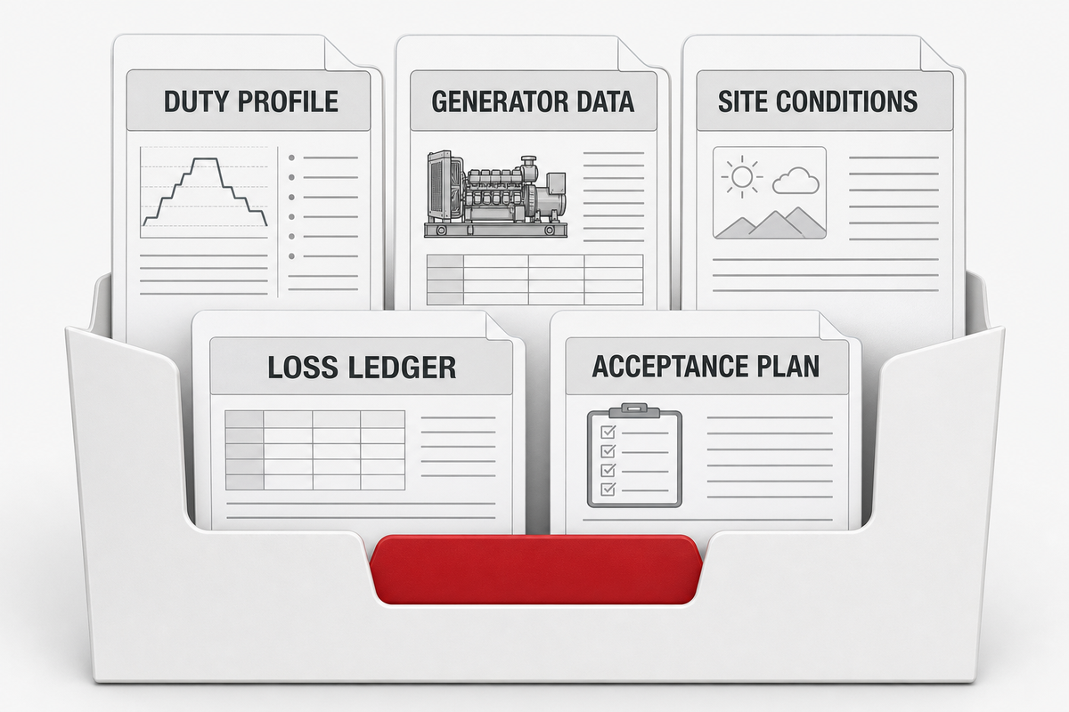
Bring the nitrogen demand profile, generator performance data, site conditions, loss ledger, and acceptance plan into one engineering discussion. That gives each supplier the same problem to solve and makes the resulting proposals comparable.
Use the U.S. Department of Energy’s compressed-air system sourcebook as an independent checklist for demand, pressure, storage, controls, and measurement inputs before requesting proposals.
Engineering note: This guide is a preliminary sizing and verification framework. Final selection of equipment, pressure protection, air quality, ventilation, and electrical design, and codes, should be done by qualified persons, as well as the determination of commissioning criteria, for the actual installation.
// SYS-DOC: WHY I WRITE THIS
[01] About PanGeng
PanGeng is an industrial gas compressor manufacturer based in Bengbu, Anhui, China. Since 2009, we have focused on the design, R&D, production, and manufacturing of customized gas compressor systems for oilfield, chemical, energy, hydrogen, nitrogen, biogas, and industrial air applications.
[02] Our Expertise
We write compressor guides based on real manufacturing and engineering experience, including hydrogen compressors, nitrogen compressors, booster compressors, medium and high-pressure air compressors, oilfield nitrogen injection systems, biogas compressors, and OEM/ODM custom compressor solutions.
Our engineering team supports customers from application analysis and compressor selection to production, factory testing, commissioning, spare parts, and after-sales service.
[03] Why You Can Trust This Content
The technical information in our articles is based on PanGeng’s in-house compressor design and manufacturing experience, current product capabilities, and project support for industrial clients in global markets. Our goal is to help buyers understand compressor types, pressure ranges, gas requirements, customization options, and long-term operating costs before making a purchasing decision.
CONTACT PROFILE
AUTHORITATIVE SOURCE
NAME
PanGeng Engineering Team
BRAND
PanGeng
COUNTRY
China
MODEL
B2B / OEM & ODM
EMAIL
pg20090705@163.com
PHONE
0552-4958225
WEBSITE
pgcompress.com