Get in Touch with Pangeng

Nitrogen Gas Compressor Sizing: Flow, Pressure, Purity, and Storage Buffer Guide

Contents
show
Updated August 2026
Nitrogen gas compressor sizing is the process of matching normalized flow, inlet pressure, discharge pressure, purity, duty cycle, and usable storage buffer to the real nitrogen source and point of use. Treat it as a pre-RFQ engineering worksheet, then ensure the final stage count, compressor type, pressure-vessel code, compressor receiver, and safety controls are confirmed with the manufacturer or designer.
Rarely can a nitrogen package be sized from a catalog nameplate alone. Catalog capacity such as 300 Nm3/h changes meaning when suction pressure, delivery reach, short high-flow draws, dryer location, or a 99.999% high-purity nitrogen specification adds pressure drop to the package. That’s why this guide separates these five questions that often get mixed together: how much nitrogen you need, at what pressure, at what purity, for how long, and with how much storage to support it.
PG Compressor provides a nitrogen compressor range context of 200-1200 Nm3/h, up to 50 MPa, and up to 99.999% purity for its nitrogen compressor pages. Treat those figures as a first-party RFQ range reference, not a universal sizing rule. Final machinery selection depends on the actual site conditions, controls, the nitrogen source, and the acceptance test criteria.
Quick Specs
| Main sizing inputs | Normal flow, reference conditions, actual suction temperature, inlet pressure, discharge pressure, purity, dew point, demand profile, and buffer recovery time |
| Flow units to clarify | Nm3/h, SCFM, sccm, or actual inlet m3/h; every value needs its reference temperature and pressure basis |
| Pressure boundary | Size to delivered end-use pressure after valves, dryers, filters, piping, regulators, and receiver location losses |
| PG range context | Published nitrogen compressor range: 200-1200 Nm3/h, up to 50 MPa, up to 99.999% purity |
| Safety boundary | Nitrogen can displace oxygen; OSHA defines an oxygen-deficient atmosphere as less than 19.5% oxygen by volume |
The Pre-RFQ Inputs You Need Before Sizing a Nitrogen Gas Compressor
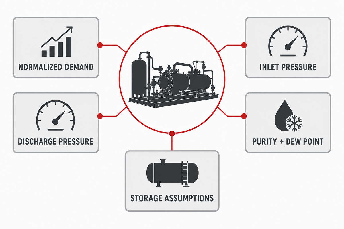
Before asking a supplier to size a nitrogen compressor, assemble the nitrogen demand, reference flow basis, inlet pressure, discharge pressure, nitrogen purity, dew point, demand profile, and storage assumptions. Without this input, the supplier must guess, and those guesses can lead to oversizing, short cycling, high horsepower, or a package that can’t hold pressure during peak demand.
Begin compressor sizing with a short pre-RFQ data pack. It should describe the nitrogen source, the process that consumes the gas, and the pressure band that must be available at the actual point of use. A PSA nitrogen generator, membrane system, bulk nitrogen source, or existing low-pressure storage header can all feed a booster, but each creates a different suction-pressure profile. A compressor chosen for a steady inlet may underperform if the real inlet pressure varies during regeneration, batch-filling, or downstream valve events.
This worksheet is purposely conservative. It doesn’t replace the local pressure-vessel review, NFPA compressed-gas code review, CGA, or ASME compressor performance standards, and it isn’t a safety standard. Its purpose is to keep buyers from submitting an RFQ that says only “need nitrogen compressor, 300 Nm3/h, 30 bar.” That single sentence masks the reference conditions, the actual suction flow, purity target, storage recovery, and pressure losses that determine whether a rotary screw, reciprocating, diaphragm, centrifugal, or booster compressor is even within the right technology range.
Write pressures in a single system before comparing. While a statement like 145 pounds per square inch, 10 barg, or 1 MPa may describe roughly comparable pressure ranges, the supplier still needs to know whether this is a gauge or an absolute. That same discipline applies to a 5-10 psig blanket, a 30-60 minute receiver recovery target, or a high-pressure batch-filling duty.
- Normalize the flow – state Nm3/h, SCFM, or sccm with reference temperature and pressure, then identify actual inlet conditions.
- Define the pressure job – record minimum suction pressure, maximum suction pressure, target discharge pressure, and delivered end-use pressure.
- Lock the quality target – specify purity, dew point, oil carryover tolerance, particles, and whether the compressor package must be oil-free.
- Map the demand profile – split continuous load, peak draw, purge, leakage, standby, batch filling, and receiver recovery.
- Validate the package boundary – ask the manufacturer to check compressor type, stage count, cooling, controls, pressure vessel rating, and acceptance testing.
Following these five steps gives the buyer a meaningful technical discussion with RFQ’d hardware instead of incomparable catalog items. Operations, maintenance, utilities, and procurement can all see the assumptions behind compressor capacity and power requirement numbers.
| Input | Why it matters | Example to send | Validation owner |
|---|---|---|---|
| Normal flow rate | Sets baseline compressor capacity before peaks or recovery loads. | 260 Nm3/h at stated normal conditions | Process owner plus supplier |
| Reference conditions | Prevents mixing normal, standard, and actual flow units. | 0 C and 101325 Pa, or site-specific standard basis | Engineering |
| Suction pressure range | Controls pressure ratio, actual inlet volume, stage count, and turndown. | 8.0-10.5 barg from generator header | Utilities plus supplier |
| Discharge pressure | Must cover end-use pressure after losses, not just compressor outlet pressure. | 35 barg at machine inlet after dryer and regulator | Process engineering |
| Purity and dew point | Determines generator/treatment needs, oil-free requirement, and pressure drop. | 99.99% N2, oil-free, dew point limit stated | Quality or process owner |
| Demand profile | Separates average load from peak flow, purge, cylinder filling, or recovery duty. | Continuous 260 Nm3/h plus 60 Nm3 purge over 12 minutes | Operations |
| Storage buffer band | Determines whether a receiver can cover short draws without a larger compressor. | Receiver from 30 barg down to minimum 20 barg, recover in 20 minutes | Engineering plus safety |
Flow Rate: Convert Demand Into the Right Nitrogen Compressor Capacity
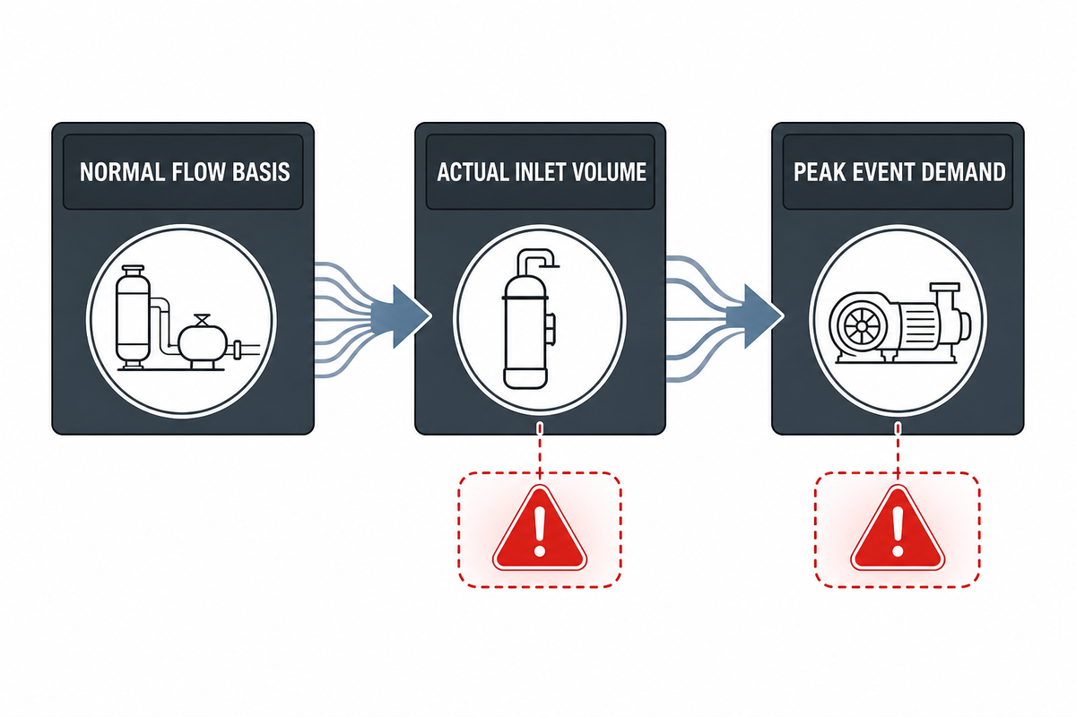
Required nitrogen flow rate is determined by converting process consumption into a common reference basis, then adding purge, leakage, peak draw, and storage recovery demand. Use normal or standard flow for comparison, but check actual inlet volume because the compressor inlet sees real temperature and pressure, not an ideal catalog condition.
Flow confusion is the fastest path to wrong compressor capacity. Nm3/h, SCFM, sccm, and actual m3/h aren’t interchangeable unless the temperature and pressure basis are defined. NIST gas-flow conversion guidance shows that standard volumetric values depend on reference assumptions, and even sccm can be used with different temperature assumptions. In practical RFQ terms, “300” isn’t a complete flow rate until it says 300 of what, at which reference condition, entering the compressor at which suction pressure and temperature.
Don’t copy an air compressor size chart into a nitrogen duty without checking the gas basis. Standard cubic feet per minute is tied to a standard condition, while actual airflow at the compressor inlet changes with atmospheric pressure, temperature, and suction pressure. If the plant team records flow measurement in cubic foot units or pounds per square inch, convert those values before comparing them with Nm3/h, barg, or MPa.
Air-compressor shortcuts need a boundary check here. A plant team may know how to size an air compressor for industrial air, air tools, tool CFM requirements, or a shop air supply, but that compressor sizing calculation does not transfer directly to sizing nitrogen compression equipment. Air flow, air treatment, and air compressor solutions help teams choose the right air compressor for plant utilities; nitrogen duty adds purity, generator output, dew point, storage recovery, and oxygen-displacement review before the correct size can be selected.
The same boundary applies when determining the right type of compressor. Rotary screw air compressor catalogs can be useful background for air service, yet the right compressor for your needs in nitrogen service depends on gas source, suction pressure, discharge pressure, duty cycle, and purity. PSA and membrane systems are common types of nitrogen generators; membrane nitrogen generators use semi-permeable membranes to separate nitrogen from compressed air, so generator pressure drop and outlet purity still belong in the RFQ. A supplier case study can be useful only when it states the duty inputs, not just the model name.
Start with the process demand that can’t be interrupted. Then add loads that appear only during a shift: purge gas, leakage, pressure testing, tool change blow-off, cylinder topping, or receiver recovery after a batch draw. If a nitrogen generation system feeds the compressor, also confirm whether the generator can supply that flow at the required purity while the compressor is recovering the receiver. A smaller nitrogen generator paired with a large booster may still starve the inlet if the generator can’t sustain the normal flow.
Engineering note
One useful RFQ flow line can read: “260 Nm3/h continuous demand, stated at 0 C and 101325 Pa; actual suction gas 25 C; inlet pressure 8-10.5 barg; purge event 60 Nm3 over 12 minutes; receiver must recover within 20 minutes.” That gives the supplier enough information to calculate compressor capacity and check air delivery, compressor power, cooling, and controls.
Do not compare compressor capacity until the flow basis, suction pressure, delivered pressure, purity limit, and receiver recovery target are written on the same sheet.
How is the required nitrogen flow rate determined for a specific application?
For a steady application, the flow rate is the continuous volume of nitrogen required to keep production running, plus a margin that the supplier validates. For an intermittent application, the peak draw and duration matter more than the hourly average. A laser cutting line may need pressure stability during short cuts, while a blanketing system may need low but reliable flow for long periods. Cylinder filling may need high pressure and batch recovery instead of steady flow.
An illustrative example shows the logic. Suppose a process uses 260 Nm3/h continuously and has a 60 Nm3 purge once per hour. Averaged over the hour, the purge is only 60 Nm3/h. When the plant wants that purge volume restored in 20 minutes, however, the recovery duty is equivalent to 180 Nm3/h during that recovery window. Final compressor capacity isn’t automatically 440 Nm3/h, because the receiver, inlet supply, controls, and allowable pressure band all matter. But the example proves why average flow alone isn’t enough for determining the correct compressor size.
Pressure: Size for Suction Pressure, Discharge Pressure, Stage Count, and Delivery Losses
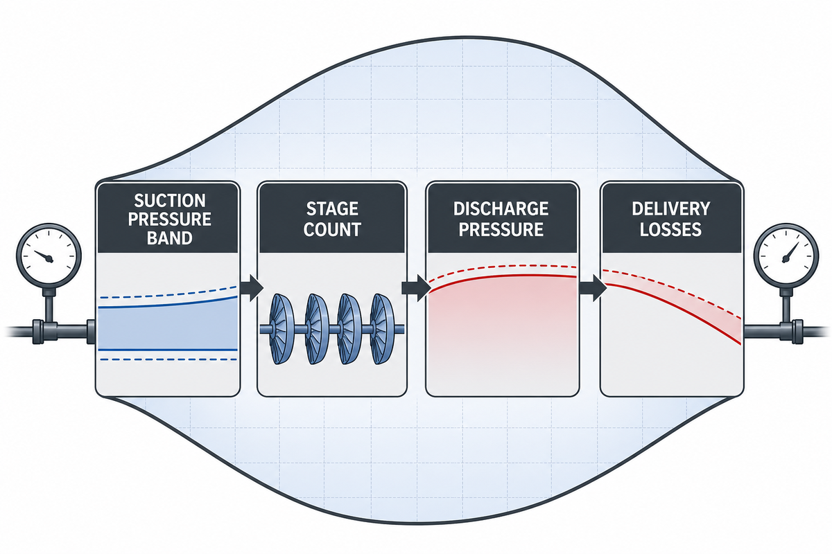
Required pressure means delivered pressure at the process, not merely the compressor discharge rating. Calculate from minimum suction pressure to required end-use pressure after dryers, filters, valves, regulators, piping, receiver placement, and expected pressure drop. Then check the compressor technology envelope and stage count.
Pressure sizing begins at the inlet. A booster compressor raising nitrogen from a generator header has a different job from a compressor pulling from low-pressure storage or a bulk supply regulator. Minimum suction pressure controls the worst-case pressure ratio, while maximum suction pressure affects mechanical limits and controls. If you size only from a nominal inlet value, the selected machinery may be acceptable on a good day and unstable when the upstream nitrogen generator is regenerating or the plant is drawing peak flow.
Compression also must pressurize the system at a rate the process can accept. Rapid pressurization can add heat, valve stress, kinetic energy in moving gas, and potential energy in stored pressure, so pressure testing and cylinder filling need a controlled ramp, not only a final pressure number. That’s why a reciprocating compressor, rotary-screw compressor, or booster compressor selection should be reviewed against the real pressure profile.
ASME PTC 10-2022 treats compressor thermodynamic performance around known or measurable gas properties, specified conditions, delivered gas quantity, pressure rise, shaft power, efficiency, surge point, and choke point. That matters because compressor sizing isn’t just “more psi.” Centrifugal units have surge and choke constraints; reciprocating compressors require stage and rod-load checks; rotary screw and booster packages have turndown, heat, and oil or seal boundaries. Right selection means the operating range covers the real inlet-to-discharge map.
Delivery losses deserve their own line in the RFQ. ORNL pipe-sizing calculator documentation treats pressure drop as a piping sizing variable, and undersized piping can reduce pressure available at end-use equipment. That same principle applies to filters, dryers, aftercoolers, check valves, regulators, long distribution runs, and receiver location. When the process needs 30 barg at the machine inlet, the compressor package may need to discharge higher than 30 barg so the system still meets the process during flow. For very high-pressure service, review high-pressure nitrogen booster compressor models only after the suction and end-use pressure band is defined.
Low-pressure supply plus booster
- Usually starts from a nitrogen generator, bulk supply, or storage header.
- Worst-case inlet pressure drives pressure ratio and actual inlet volume.
- Good for raising available nitrogen to a higher final pressure.
- Needs protection against upstream starvation and pressure swing.
Integrated compressor package
- May include compression, cooling, treatment, controls, and receiver coordination.
- Can be specified around a complete duty profile and acceptance test.
- Useful when site utilities, purity, and discharge pressure are linked.
- Needs clear scope boundary so generator, compressor, and storage are not mismatched.
What Amount of Pressure Do I Need?
Ask for the pressure that the process actually needs at the point of use. Then work backward through the system. Where a regulator, dryer, filter bank, long pipe run, or receiver location consumes pressure, include that loss before choosing discharge pressure. Use absolute pressure for calculations when comparing pressure ratio, and state psig, barg, MPa, or pounds per square inch consistently in the RFQ.
Purity, Dew Point, Oil Carryover, and Oxygen-Deficiency Risk
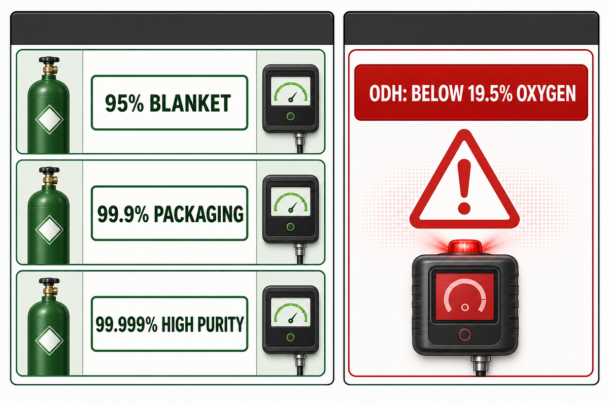
Nitrogen purity doesn’t directly set compressor displacement, but it changes the system that surrounds the compressor. Higher purity can require different generator operation, filtration, drying, oil-free compression, seal choices, purge logic, and safety review. Also treat nitrogen release as an oxygen-displacement hazard, especially in rooms, pits, containers, or poorly ventilated areas.
Purity targets such as a 95% nitrogen blanket, a 99.9% packaging stream, and a 99.999% high-purity nitrogen duty can require very different upstream and downstream equipment. AirBestPractices notes that nitrogen purity should be selected by application need rather than by assuming the highest purity is always better. Higher purity may reduce generator output, increase compressed air needs, add pressure drop, or require stricter contamination control. That’s why purity level belongs in the compressor sizing data pack, even though it isn’t the same as flow rate.
Nitrogen generation also changes the surrounding utility load. Pressure swing adsorption relies on adsorption media, while membrane systems use a semipermeable membrane to separate nitrogen from the compressed air stream. Neither option should be confused with liquid nitrogen supply, and neither behaves like an electric generator that produces flow independently of compressed air systems. For efficient energy use, a manufacturing site should match purity to the real oxygen limit, product risk, and investment case instead of automatically specifying the highest purity.
Oil-free compression is another boundary to decide early. Where gas is used for laser cutting applications, food packaging, electronics, pharmaceutical blanketing, high-purity nitrogen, or any process that can’t tolerate compressor oil, specify oil-free or define the downstream filtration and acceptance limit. When oil-lubricated machinery is acceptable, say so explicitly and ask the supplier to define filters, activated carbon, maintenance intervals, and carryover guarantees. Don’t assume “nitrogen” automatically means clean gas after compression.
Safety review isn’t optional. OSHA defines an oxygen-deficient atmosphere as one containing less than 19.5% oxygen by volume. Nitrogen is inert for many industrial applications, but that same property makes it dangerous when it displaces breathable air. Any sizing request that includes indoor venting, purge discharge, relief valves, cylinder filling, or receiver blowdown should trigger ventilation, gas detection, confined-space, and emergency-response review by the site safety team.
Nitrogen Purity: What Do I Need and Why Is It Important?
Use the purity that protects the product or process with a documented margin. Too little purity can damage quality; too much purity can increase energy cost, reduce nitrogen generator output, or force larger upstream compressed air systems. For generator-fed compressors, compare PSA vs membrane nitrogen generator selection before final compressor capacity is locked, because generator technology can affect available flow, purity, and pressure.
Storage Buffer: How to Decide Between a Larger Compressor and a Receiver
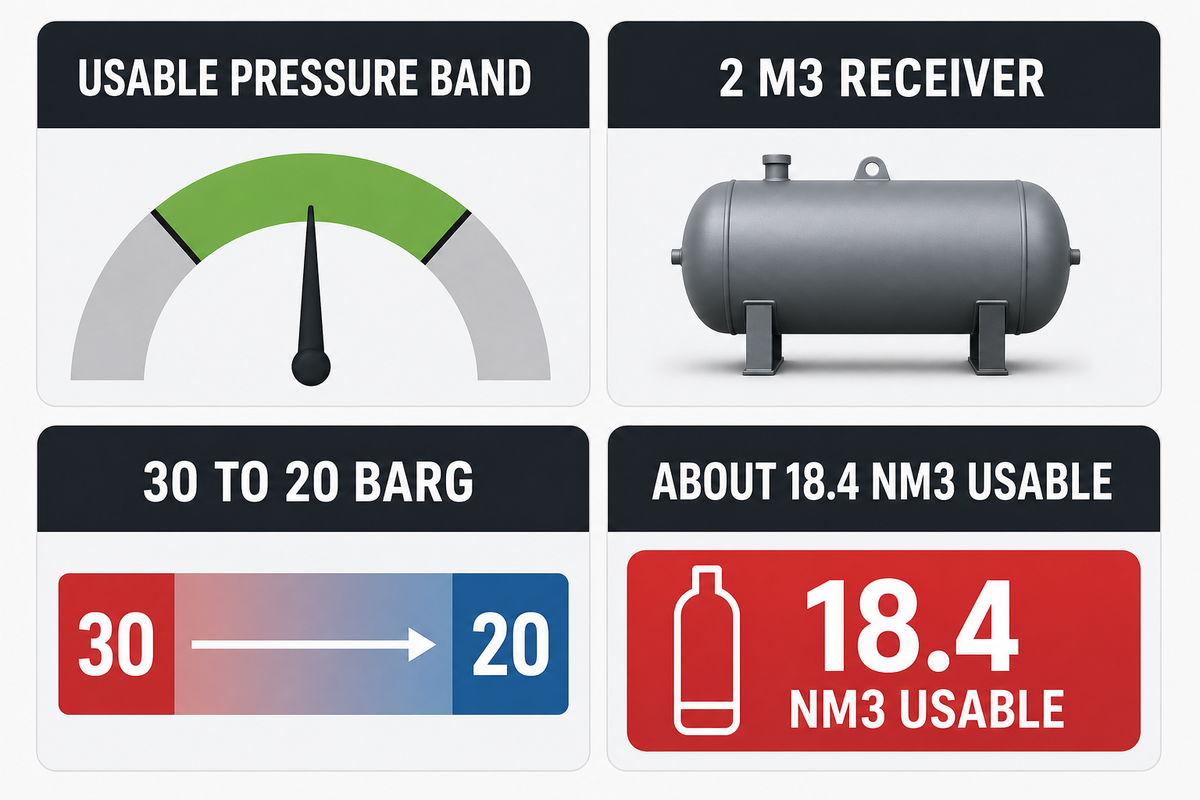
Storage can cover short peak draws, but it can’t replace missing average compressor capacity. Size the usable buffer from the pressure band between maximum receiver pressure and minimum process pressure, then check how quickly the compressor can recover that usable volume while the process continues drawing gas.
Receiver sizing is often described as “add a bigger tank,” but the tank’s full geometric volume isn’t what the process can use. Usable volume is the gas released between the high pressure and the lowest pressure that still satisfies the process. At 30 barg, a receiver that must stop drawing at 20 barg has a much smaller usable band than one allowed to draw down to 10 barg. When the downstream machine needs a stable inlet, the minimum pressure can be set by quality, cycle time, or valve behavior rather than by the tank’s mechanical rating.
For illustration only, consider a 2 m3 receiver cycling between 30 barg and 20 barg at about 20 C. Using absolute pressure, that’s roughly a 10 bar pressure difference. On a normal 0 C and 1.013 bar basis, the usable gas is approximately 2 x 10 / 1.013 x 273 / 293, or about 18.4 Nm3 before allowance for regulator, piping, dryer, and control losses. This example follows the same reference-condition discipline behind the NIST pressure and gas-flow conversion reference. When the application draws 60 Nm3 in a short event, that receiver alone can’t cover the entire event. Either the receiver volume, pressure band, compressor recovery rate, or process expectation has to change.
Pressure-vessel boundary
Receiver selection must be checked against the applicable pressure vessel code, relief protection, inspection rules, corrosion allowance, drainage, location, and site safety standards. This article explains pre-RFQ sizing logic, not legal certification or final vessel design.
Receiver location changes the answer. Upstream storage can stabilize the compressor inlet but may not protect the process after a dryer or regulator. Downstream storage can protect a machine but may expose the receiver to higher purity, dryer dew point, or oil-free requirements. When treatment equipment creates pressure loss, the receiver’s high and low pressure band should be defined on the same side of the treatment train as the process requirement.
| Question | If yes | If no |
|---|---|---|
| Is the average nitrogen demand below compressor capacity? | A receiver may cover short peaks. | A larger compressor or added compressor capacity is likely needed. |
| Is the usable pressure band large enough? | Calculate drawdown and recovery time. | Raise receiver pressure, increase volume, or reduce minimum pressure if the process allows. |
| Can the compressor recover while production continues? | Confirm duty cycle and motor load. | Peak events will still cause downtime or low pressure. |
| Is the receiver installed where it protects the load? | Check downstream losses and controls. | Storage may stabilize the wrong part of the system. |
Application Sizing: Laser Cutting, Blanketing, Cylinder Filling, Testing, and Packaging
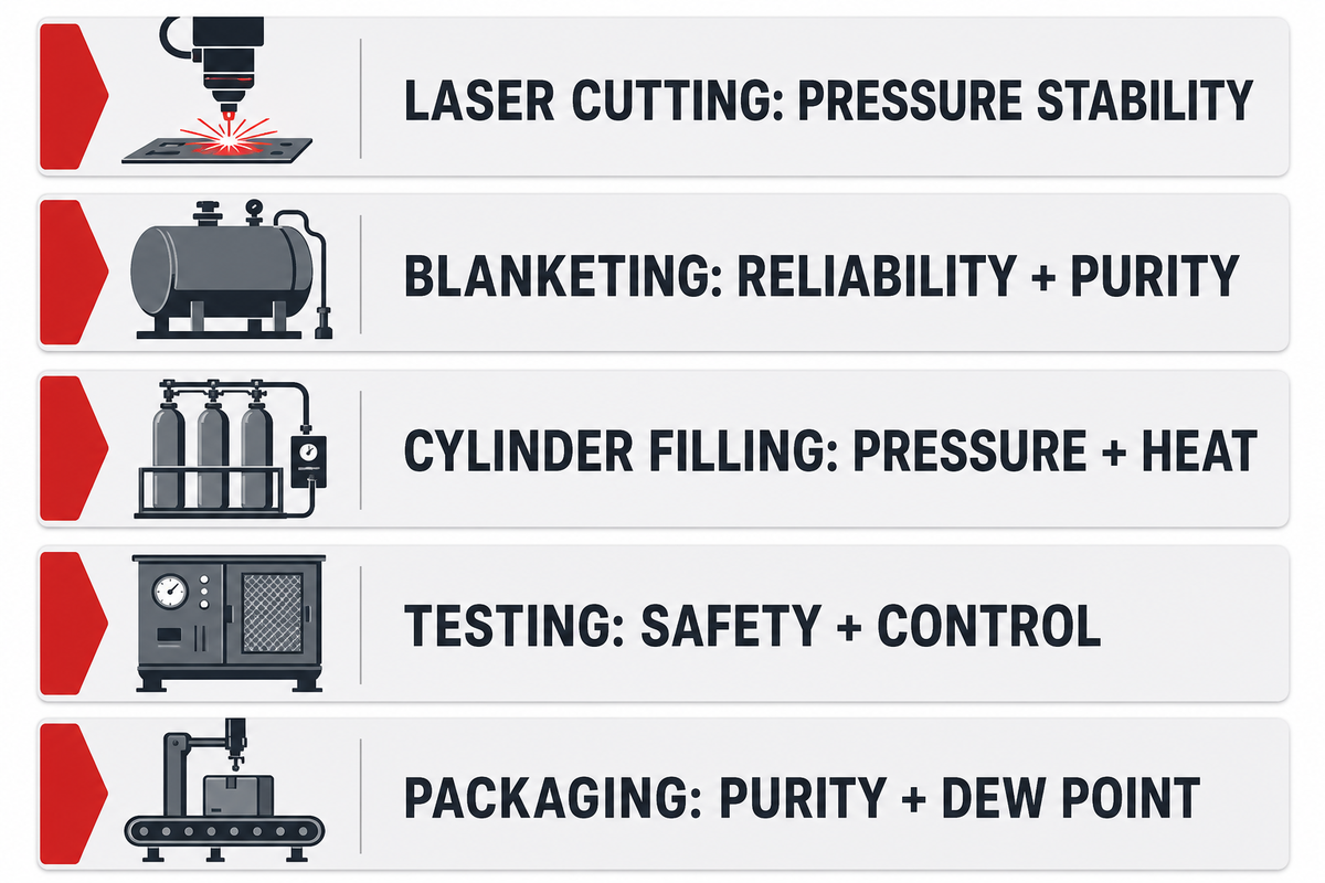
Different nitrogen applications fail for different reasons. Laser cutting is often pressure-stability sensitive, blanketing is reliability and purity sensitive, cylinder filling is pressure and heat sensitive, pressure testing is safety and control sensitive, and packaging is purity, oil, and dew point sensitive. Size the compressor around the dominant driver.
A single sizing calculation is useful only after the application is clear. For laser cutting, pressure drop during a high-flow assist-gas draw may matter more than average daily consumption. For tank blanketing, the flow can be modest but continuous supply of nitrogen, purity, and low-pressure stability may decide uptime. For cylinder filling, final pressure, filling profile, cooling, and safety valves dominate the compressor specification, while OSHA’s oxygen-deficiency boundary keeps venting and enclosed-space review visible. For packaging, purity and compressed air quality influence whether the nitrogen generation system can support the compressor without contaminating product-contact gas.
| Application type | Primary sizing driver | What to document | Common risk |
|---|---|---|---|
| Laser cutting | Peak flow and pressure stability | Cutting gas pressure, peak duration, nozzle usage, receiver band | Sizing from average flow and losing pressure during cuts |
| Tank blanketing | Reliability, purity, and low-pressure control | Blanket pressure, venting, makeup flow, oxygen target | Oversizing pressure when the real issue is control stability |
| Cylinder filling | Final pressure, filling rate, heat, and batch recovery | Cylinder rating, target psig or MPa, cascade plan, fill time | Ignoring temperature rise and safety-device requirements |
| Pressure testing | Controlled pressurization and safety margin | Test pressure, ramp rate, hold time, isolation volume | Treating a test as normal production flow |
| Food packaging | Purity, oil-free gas, dew point, and hygiene | Nitrogen purity, oil tolerance, dryer, filtration, audit needs | Forgetting that air quality affects nitrogen quality |
| Generator-fed booster | Available inlet pressure and generator output | Generator flow, purity setpoint, inlet pressure trend, booster suction limit | Starving the booster when generator output falls at higher purity |
| Oilfield nitrogen injection | Continuous flow, high discharge pressure, and cooling | Injection pressure, flow profile, ambient temperature, power availability | Underestimating heat load, horsepower, and site utility demand |
| Leak testing and inerting | Controlled ramp rate and stable hold pressure | Test volume, pressure ramp, hold time, venting, oxygen monitor plan | Using a production-flow compressor for a safety-critical test sequence |
Application context keeps the equipment discussion focused. A product page can describe compressor models, while a sizing guide should explain how an engineer or buyer defines the duty. Once your application driver is clear, your custom nitrogen compressor application can be reviewed against a valid duty profile instead of a horsepower-only request.
The 5-Part Flow-Pressure-Purity-Buffer Risk Matrix
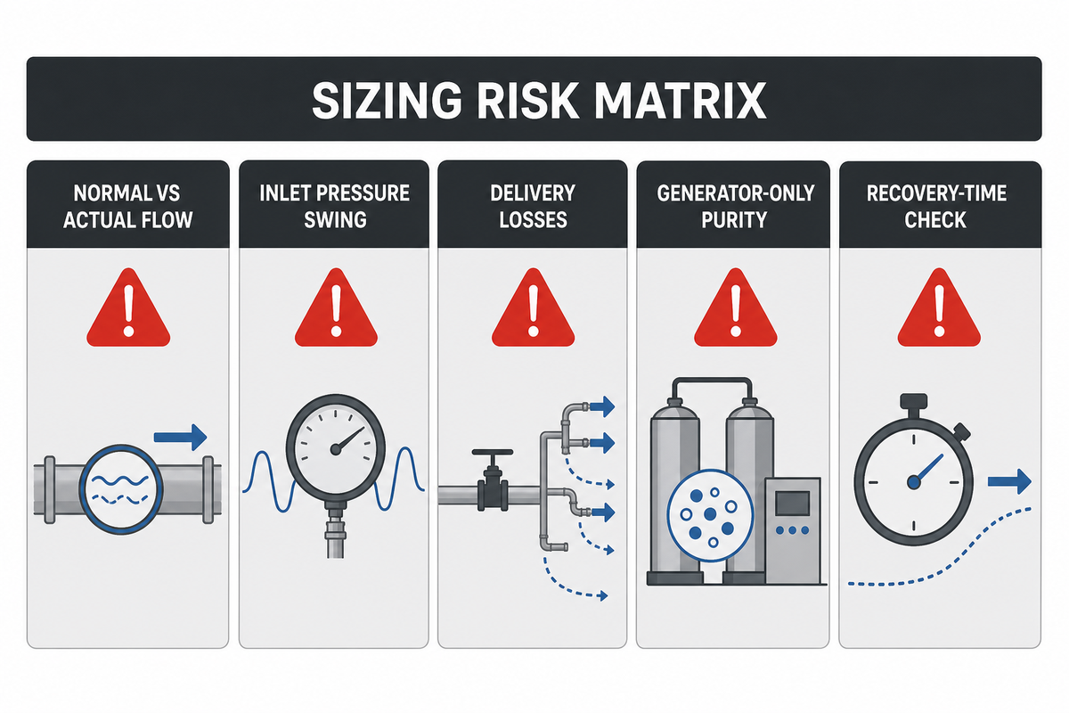
The most common sizing mistakes are mixing normal and actual flow, assuming stable inlet pressure, sizing discharge pressure without delivery losses, treating purity as generator-only, and using receiver volume without a recovery-time check. Each mistake can create a right-looking compressor that performs poorly in the actual system.
It isn’t uncommon in gas compressor engineer forums or trade publications to find buyers or engineers beginning with one known, whether normal flow or final delivery pressure, and as the process is considered, find that gas properties, ambient, inlet, ratio or discharge pressure or buffer drawdown necessitates changing the compressor size to match the application requirements. The same risk matrix should stay tied to flow-basis conversion, compressor performance variables, and pressure-drop review. While it’s true that one need not employ full scale process simulation, one should identify and reveal assumptions.
Do
- State normal flow and actual suction conditions in the same request.
- Ask the supplier to confirm pressure ratio, stage count, and operating envelope.
- Show peak demand and recovery time instead of only daily average flow.
- List purity, dew point, oil tolerance, and treatment pressure losses.
- Locate the receiver relative to dryers, filters, regulators, and the end-use machine.
Don’t
- Assume a compressor with the right nominal flow has the right inlet volume.
- Use psig, barg, and MPa interchangeably without conversion.
- Treat high purity as free if it reduces generator output or adds pressure drop.
- Let a storage tank mask inadequate average compressor capacity.
- Skip oxygen-deficiency, pressure-vessel, relief, and ventilation review.
| Risk | Symptom | Pre-RFQ check |
|---|---|---|
| Unit mismatch | Capacity looks correct but compressor cannot supply actual inlet volume. | Ask for reference conditions and actual suction conversion. |
| Inlet swing | Package trips, overheats, or misses pressure during upstream low-pressure events. | Provide minimum and maximum inlet pressure under real operation. |
| Delivery loss | Compressor outlet pressure is high enough, but machine pressure is low. | Add dryers, filters, valves, regulators, and piping pressure drop. |
| Purity penalty | Generator output falls or treatment limits flow at higher purity. | Confirm generator capacity at target purity and dew point. |
| Buffer illusion | Receiver covers one event but pressure falls during repeated draws. | Calculate usable volume and recovery while the process is still running. |
Nitrogen Compressor RFQ Checklist: What to Send a Manufacturer
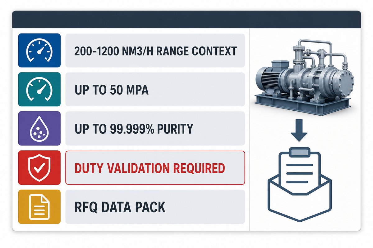
A strong nitrogen compressor RFQ includes gas source, normal flow, actual suction conditions, discharge pressure, purity, dew point, oil tolerance, demand profile, receiver data, site utilities, controls, certification requirements, and acceptance-test criteria. Send the assumptions, not only a model size or horsepower target.
Manufacturers can do better sizing when the RFQ reads like a system description. Anhui PanGeng Gas Compressor Co., Ltd. describes itself as a company that designs, researches, produces, and manufactures complete gas compressor systems for industrial markets. That kind of supplier conversation should include more than a line item; it should include enough data to decide whether the package is a booster compressor, a multi-stage reciprocating package, a rotary screw package, an oil-free package, or a complete system with controls and storage.
PG Compressor’s published nitrogen compressor range is useful RFQ context: 200-1200 Nm3/h, up to 50 MPa, and up to 99.999% purity. Those numbers show the product family can cover many industrial duties, but they don’t remove the need for duty validation. Use the table below as a data pack before discussing custom nitrogen compressor solutions.
RFQ Data Pack Checklist – copy these into your quote request:
| Parameter | Recommended range | Why it matters | How to verify |
|---|---|---|---|
| Normal flow | Use measured process demand; PG range context is 200-1200 Nm3/h | Sets compressor capacity before buffer and peaks | Metered demand log or process balance |
| Suction pressure | Minimum, normal, and maximum inlet pressure | Controls actual inlet volume and pressure ratio | Header pressure trend under peak demand |
| Discharge pressure | End-use pressure plus verified system losses | Avoids low pressure after dryers, filters, and piping | Pressure-drop calculation and site test |
| Purity and dew point | Application target, up to published 99.999% range where applicable | Defines generator, dryer, filter, and oil-free needs | Gas analyzer, dew point test, acceptance certificate |
| Duty cycle | 8-24 h/day, starts/hour stated, 15 min batch profile attached | Prevents short cycling and overheated machinery | PLC trend or operating schedule |
| Storage buffer | Receiver volume, high pressure, minimum process pressure, recovery time | Shows whether storage can cover peak draw | Drawdown calculation and functional test |
| Code and controls | Pressure-vessel code, relief devices, shutdowns, oxygen monitoring as needed | Aligns mechanical scope with site safety requirements | P&ID review, certificates, FAT or SAT checklist |
When your procurement team already uses a form, attach the worksheet as a technical appendix. Otherwise, pair it with a nitrogen compressor specification checklist so commercial comparison doesn’t happen before engineering scope is stable. Horsepower, delivery time, price, and warranty are important, but they should be compared only after the same flow, pressure, purity, and buffer assumptions are being used.
Nitrogen Compressor Sizing Review
Send your normal flow, pressure band, purity target, duty profile, and storage assumptions to PG Compressor so the compressor package can be checked against the real system boundary.
Key takeaway
Do not size a nitrogen compressor from flow alone. A workable size appears only after reference conditions, inlet pressure, delivered pressure, purity, demand profile, and usable storage buffer are checked as one system.
FAQ
How do you size a nitrogen gas compressor?
Sizing starts with gas demand and reference conditions, then validates suction pressure, delivered pressure, purity, duty cycle, receiver recovery, and package safety as one system.
Size it from the gas demand first, not from a catalog model. Collect the normal flow rate, reference conditions, actual inlet pressure and temperature, target discharge pressure, required purity, allowable dew point, oil tolerance, and duty pattern. Then check whether peak demand can be handled by compressor capacity alone or whether a receiver should cover short draws while the compressor recovers.
What information is needed to size a nitrogen compressor?
Useful requests send normal flow, actual suction conditions, discharge pressure, delivered end-use pressure, purity, dew point, duty profile, receiver data, utilities, controls, and safety constraints.
Useful sizing requests include normal flow, minimum and maximum inlet pressure, required discharge pressure, delivered end-use pressure, purity, dew point or oil limits, ambient conditions, hours per day, start-stop limits, storage volume if any, and the application. Missing one of those fields forces the supplier to assume a margin, which can raise cost or create a system that can’t hold pressure during peak demand.
How do you calculate nitrogen compressor flow rate?
Flow calculation converts process consumption into a normal flow basis, adds purge and leakage, then separates peak draw, average demand, and receiver recovery duty from hourly capacity.
Start with the process consumption in normal units such as Nm3/h or SCFM, then add purge, leakage, and recovery demand instead of using only average production flow. For intermittent demand, calculate the peak draw and duration separately. Final compressor flow is the rate needed to refill the usable storage band within the required recovery time while the process continues operating.
Do I need an oil-free nitrogen compressor?
Oil-free compression is needed when the process cannot tolerate compressor oil; the RFQ should also state filtration, maintenance, service access, oil monitoring, and carryover limits.
Oil-free compression is common for high-purity nitrogen, laser assist gas, food packaging, electronics, pharmaceutical blanketing, and other quality-sensitive duties. Oil-lubricated compressors may still work for less sensitive applications, but the RFQ should state filtration, maintenance, and acceptable oil carryover so purity isn’t assumed.
Can a storage tank replace a larger nitrogen compressor?
Storage tanks can cover short peaks between high and minimum process pressure, but they cannot replace missing average compressor capacity or inadequate recovery flow during peak demand.
Storage tanks can cover short spikes, but they can’t replace missing average compressor capacity. The tank only provides usable nitrogen between a high pressure and a minimum process pressure. When the process continues drawing gas faster than the compressor refills that usable band, pressure will still fall. That’s why receiver volume, compressor flow, recovery time, and pressure limits must be checked as one system.
What is the difference between a nitrogen compressor and a nitrogen booster?
Booster packages raise an existing nitrogen stream to higher pressure, while full compressor systems may include compression, gas treatment, controls, storage coordination, and acceptance testing.
A nitrogen compressor can describe the full package used to compress nitrogen from a source to the required pressure. Nitrogen booster usually refers to a machine that raises an already available nitrogen stream, often from a generator, bulk supply, or lower-pressure storage, to a higher final pressure.
What pressure is used for nitrogen cylinder filling?
Cylinder filling pressure depends on cylinder rating, gas temperature, filling procedure, fill profile, cooling method, safety valves, and whether the duty is batch or continuous.
Cylinder-filling pressure depends on cylinder design pressure, filling standard, gas temperature, and the end-use requirement. Don’t size a booster from a single target pressure without confirming cylinder rating, safety valves, cascade storage plan, cooling, and whether the filling profile is batch or continuous.
What should I include in a nitrogen compressor RFQ?
Strong RFQs include the assumptions that decide compressor capacity, receiver sizing, treatment scope, controls, certification needs, acceptance testing, commissioning, supplier comparison, and safe site integration.
Include gas source, flow units, inlet pressure range, discharge pressure, purity, dew point, oil tolerance, duty cycle, storage volume, site utilities, controls, cooling water or air-cooling preference, certification needs, and acceptance test criteria. Attach the demand profile when the load changes during the day. For comparable bid tabs, ask every supplier to quote the same reference conditions, the same receiver high-low pressure band, the same pressure-vessel code expectation, and the same factory or site acceptance test. That keeps price, horsepower, lead time, spare parts, warranty, and commissioning scope tied to one technical basis instead of several hidden assumptions.
Related Articles
- Custom nitrogen compressor solutions – product family range and RFQ handoff.
- High-pressure nitrogen booster compressor models – booster context for high discharge pressure duties.
- PSA vs membrane nitrogen generator selection – generator-side purity and flow tradeoffs.
- Nitrogen compressor specification checklist – additional RFQ fields for compressor package comparison.
Our Perspective on Nitrogen Compressor Sizing
This guide explains nitrogen compressor sizing because flow, pressure, purity and buffer decisions are typically divided among process, utilities, safety and procurement functions. The worksheet is meant to clarify those assumptions prior to submitting a quote but doesn’t interfere with final compressor or code selection to be done by the responsible supplier and site engineers. Final review by Anhui PanGeng Gas Compressor Co., Ltd. technical team.
References & Sources
- Pressure and Gas Flow Unit Conversions – National Institute of Standards and Technology
- PTC 10 – Axial and Centrifugal Compressors – The American Society of Mechanical Engineers
- Pipe Sizing Calculator Documentation – Oak Ridge National Laboratory Industrial Resources
- Selecting the Appropriate Nitrogen Gas Purity Level for Your Application – Compressed Air Best Practices
- 29 CFR 1910.146 Permit-Required Confined Spaces – Occupational Safety and Health Administration
- Air Receiver Tank Care Guide: Sizing, Safety and Storage – Compressed Air Best Practices
- NFPA 55 Standard Development – National Fire Protection Association
- Compressed Gas Association Standards and Safety Resources – Compressed Gas Association
// SYS-DOC: WHY I WRITE THIS
[01] About PanGeng
PanGeng is an industrial gas compressor manufacturer based in Bengbu, Anhui, China. Since 2009, we have focused on the design, R&D, production, and manufacturing of customized gas compressor systems for oilfield, chemical, energy, hydrogen, nitrogen, biogas, and industrial air applications.
[02] Our Expertise
We write compressor guides based on real manufacturing and engineering experience, including hydrogen compressors, nitrogen compressors, booster compressors, medium and high-pressure air compressors, oilfield nitrogen injection systems, biogas compressors, and OEM/ODM custom compressor solutions.
Our engineering team supports customers from application analysis and compressor selection to production, factory testing, commissioning, spare parts, and after-sales service.
[03] Why You Can Trust This Content
The technical information in our articles is based on PanGeng’s in-house compressor design and manufacturing experience, current product capabilities, and project support for industrial clients in global markets. Our goal is to help buyers understand compressor types, pressure ranges, gas requirements, customization options, and long-term operating costs before making a purchasing decision.
CONTACT PROFILE
AUTHORITATIVE SOURCE
NAME
PanGeng Engineering Team
BRAND
PanGeng
COUNTRY
China
MODEL
B2B / OEM & ODM
EMAIL
pg20090705@163.com
PHONE
0552-4958225
WEBSITE
pgcompress.com


Trending now


![Low Pressure Hydrogen Compressor Applications [Guide]](https://pgcompress.com/wp-content/uploads/2026/09/low-pressure-hydrogen-compressor-applications-blog-featured-150x150.png)