Get in Touch with Pangeng


A natural gas booster compressor raises the pressure of gas that is already above atmospheric — pipeline takeoff gas, wellhead casing gas, or a low-pressure gathering stream — up to the level a downstream process actually needs. This guide walks through compression physics, the real decision points between reciprocating, screw, and centrifugal technology, a four-parameter sizing framework, how to read API 618 and NACE MR0175 without falling for vendor marketing, and lifecycle-cost math that engineering buyers use. Data comes from the U.S. Department of Energy, EIA Natural Gas Annual, Penn State Extension research on compressor stations, API 618 (6th edition, 2024), and thirty years of reciprocating booster system manufacturing practice at the Pangeng plant in Bengbu, China.
Quick Specs: Natural Gas Booster Compressor at a Glance
| Typical inlet pressure | 0.02–4.0 MPa (3–580 psi) |
| Typical discharge pressure | 0.5–50 MPa (73–7,250 psi) |
| Typical flow range | 20–3,500 Nm³/h |
| Dominant technology | Reciprocating (piston) for flows under 3,500 Nm³/h and discharge above 50 psi |
| Stage count | 2–5 (set by the per-stage compression ratio ceiling) |
| Key standards | API 618 (6th ed., 2024), NACE MR0175 / ISO 15156, ISO 9001, ASME BPVC |
| Typical service life | 20+ years with disciplined valve, ring, and packing maintenance |
What Is a Natural Gas Booster Compressor? Role in the Gas Value Chain
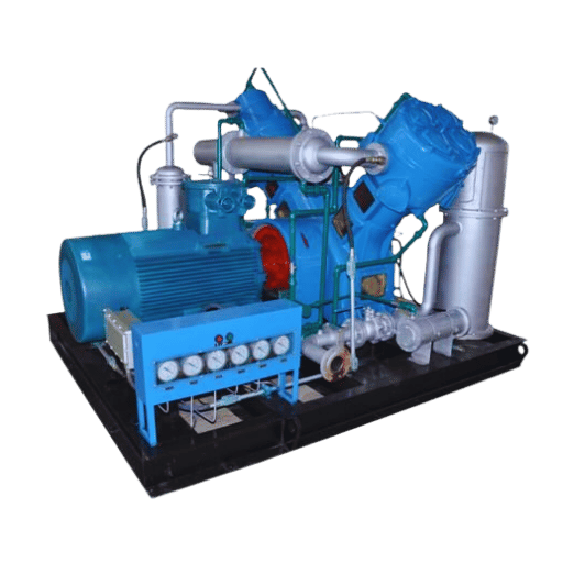
Natural gas booster compressors are secondary compression units that take gas at intermediate pressure — commonly 0.02 to 4.0 MPa suction — and raise it to the higher pressure that the next step in the value chain demands. That could mean lifting wellhead casing gas from 0.05 MPa up to a 1.8 MPa pipeline spec, topping pipeline pressure back to 4.2 MPa after 50 miles of frictional loss, or feeding a CNG fueling island at 25 MPa. What separates a booster from a primary compressor is the starting condition: gas is already above atmospheric, so each unit works at higher suction pressure, a smaller per-stage compression ratio, and generally a more steady-state duty cycle.
Placing a booster correctly means understanding where pressure is lost along the value chain. According to Penn State Extension research on natural gas compressor stations, interstate transmission pipelines operate at 800 to 1,200 psi, and compressor stations sit 40 to 70 miles apart to restore lost pressure. U.S. Department of Energy NETL data on transmission networks implies about 2.5 to 5 psi of pressure loss per mile under normal transmission conditions — a number often exaggerated in marketing copy to 5 to 15 psi per mile, which in practice only shows up on heavily loaded or undersized segments.
Four practical positions define booster duty: (1) wellhead casing gas recovery — turning annular gas that would otherwise be flared into pipeline-grade product; (2) gathering and transmission boosting — keeping throughput above contractual delivery pressure; (3) CNG vehicle fueling — lifting municipal-grade gas to 20–25 MPa storage pressure; and (4) fuel gas boost — feeding gas turbines in power plants that need 3–5 MPa nozzle pressure. Each setting demands a different compression ratio, stage count, and gas-handling approach.
For a first-principles view of booster duty in general (not only natural gas), see our background on core booster compressor mechanics, and for the distinction against primary machines, see how boosters differ from primary compressors.
How Natural Gas Booster Compressors Work — Thermodynamics and Multi-Stage Compression

At cylinder level, a reciprocating natural gas compressor works on four strokes within two mechanical events: piston retreats, suction valves open, and gas at inlet pressure fills the cylinder; piston advances, suction valves shut, gas is compressed until its pressure exceeds the discharge header, discharge valves open, and compressed gas flows out to the receiver tank. Polytropic work required for that compression rises steeply with the pressure ratio — roughly as P₂ over P₁ raised to the (γ-1)/γ — and most of that work shows up as heat.
That heat is the reason multi-staging exists. Penn State Extension field data on transmission compressor stations reports that, for every 100 psi increase in gas pressure during compression, gas-stream temperature rises by 7 to 8 °F. Running a single-stage machine from 0.1 MPa gas to 5 MPa would put discharge well above 180 °C — hot enough to degrade lube oil, carbonize valve seats, and shorten piston-ring life. Staged compression with intercooling between stages returns gas to about 40 °C before the next compression event, so each stage can work over a smaller ratio with less thermal stress.
How does a natural gas booster compressor work?
Reciprocating natural gas booster compressors work in five sequential events per stage: (1) cylinder draws in gas at inlet pressure through suction valves; (2) piston reverses direction and suction valves close; (3) gas is compressed adiabatically until its pressure exceeds discharge-side pressure; (4) discharge valves open and compressed gas flows out to the intercooler or discharge header; (5) the process repeats at the next stage, now starting from intercooled, elevated inlet pressure. Multi-stage arrangements with intercooling let a single package reach 50 MPa or more while keeping every stage below the 150 °C discharge temperature that industry practice treats as the upper bound for reliable long-term operation.
📐 Engineering Note — Stage Ratio and Discharge TemperatureIndustry practice limits per-stage pressure ratios to roughly 2.5:1 up to 4:1 for natural gas service. Running a three-stage package with 5:1 stage ratios yields a 125:1 overall compression ratio while keeping every stage below about 150 °C discharge. That 150 °C bound comes from lube-oil degradation and ring-wear acceleration rather than a single codified API clause — it is the number that consistently appears in reciprocating-compressor design practice and in API 618 vibration- and pulsation-study templates. When a stage is pushed past 4:1 for cost reasons, valve life drops by roughly half and ring-package intervals shorten accordingly.
For a broader walk-through of reciprocating and diaphragm operating cycles in general, see our booster compressor operating cycle reference. Peer-reviewed vibration data published in 2024 in the U.S. National Library of Medicine’s PMC archive on vibration and pressure pulsation in a reciprocating compressor is a rare openly-published example of API 618 and ISO 20816-1 acceptance limits tied to actual machine measurements — useful reading for anyone specifying a new booster system.
Reciprocating vs Rotary Screw vs Centrifugal — The Technology Decision
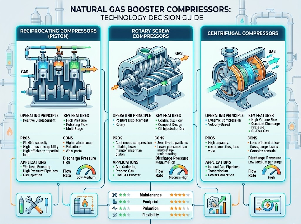
For natural gas boosting in the 20–3,500 Nm³/h flow band at discharge pressures above about 2 MPa, reciprocating piston compressors dominate, and that dominance is not marketing. It is a function of three mechanical realities: wet-gas tolerance, high-compression-ratio efficiency, and step unloading that matches fluctuating wellhead supply. Screw compressors lose ground above 50 psi (roughly 0.35 MPa) discharge because their fixed volumetric ratio does not reward the pressure lift; centrifugals are inefficient below about 5,000 Nm³/h because their impellers enter surge. Table below compares three technologies on variables that actually matter in natural gas service.
| Parameter | Reciprocating (Piston) | Rotary Screw | Centrifugal |
|---|---|---|---|
| Discharge pressure | 0.1–50 MPa (15–7,250 psi) | 0.5–4.0 MPa (73–580 psi) | 0.4–10 MPa (58–1,450 psi) |
| Flow range | 20–3,500 Nm³/h | 500–15,000 Nm³/h | 5,000–500,000+ Nm³/h |
| Isentropic efficiency | 85–92% | 72–82% | 80–88% at design point |
| Turndown range | 0–100% (step unloading) | 60–100% | 70–100% (surge limit) |
| Valve or bearing overhaul | 4,000–8,000 hr (valves) | 20,000–40,000 hr (bearings) | 40,000–80,000 hr (bearings) |
| Wet gas tolerance | Handles with upstream knockout | Requires dry, clean gas | Requires dry, clean gas |
The Pressure-Ratio Crossover Rule. Clearest selection rule for booster service comes out of the Compressor Handbook and Compressors: Selection and Sizing (3rd ed.): a single-stage machine starting from atmospheric inlet is limited to about 50 psi discharge, and below that line screw compressors hold a capital-cost advantage. In natural gas booster service, suction is already elevated, so the same 50 psi (≈0.35 MPa) threshold acts as a crossover: above it, reciprocating wins on both capital and lifecycle cost for flows under 3,500 Nm³/h; below it, rotary screw is competitive on energy and footprint. Specifying a centrifugal machine for 500 Nm³/h wellhead duty because “bigger is smoother” is the classic wrong answer — that machine spends most of its life near surge, and discharge pressure will not stay within a usable band.
“Correct sizing combined with a good understanding of the performance curve can make the difference between a system that runs smoothly for years and one that surges on every startup. The three worst choices I see are centrifugals on low-flow gathering duty, screws pushed past 50 psi discharge, and reciprocating units picked on nameplate flow without reading the turndown curve.”
✔ Advantages of Reciprocating
- Discharge up to 50 MPa in a single package
- 85–92% isentropic efficiency across a wide load band
- Step unloading enables 0–100% turndown
- Handles wet gas with upstream separation
- Compatible with H₂S-bearing sour gas under NACE metallurgy
⚠️ Limitations of Reciprocating
- Valve service interval only 4,000–8,000 hr vs 20,000+ hr for screw
- Pulsation demands proper bottle and piping design
- Heavier per unit flow than rotary technologies
- Foundation and vibration isolation costs are real
- Skid footprint larger than screw for mid-pressure duty
For a broader technology-by-technology comparison beyond natural gas service, see our breakdown of booster compressor types and a deeper treatment of the reciprocating side in reciprocating compressor fundamentals.
Where Natural Gas Booster Compressors Are Used — Applications Across the Value Chain
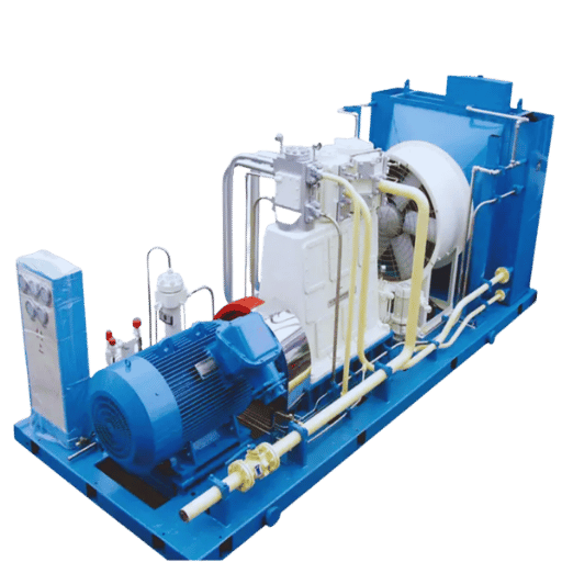
Dry natural gas production in the U.S. reached 37.72 trillion cubic feet in 2024, and consumption averaged a record 90.3 Bcf/d according to EIA monthly tracking. Moving that volume from wellhead to end user requires compression at roughly five distinct duty points, and natural gas boosters are workhorses at three of them.
Casing gas recovery captures low-pressure annular gas that would otherwise be flared or vented when reservoir pressure drops below pipeline delivery requirements. Inlet pressure can fall to 0.02 MPa on mature wells, and gas composition varies from 60% to 85% methane with heavier hydrocarbons, CO₂, water vapor, and often H₂S. Standard casing-gas packages take that stream up to 1.8 MPa for pipeline injection. Scenario: a brownfield operator in West Texas saw gathering pressure fall from 0.15 MPa to 0.05 MPa over eighteen months as three nearby wells aged. Their original rotary-screw skid had been sized for the higher inlet; by the time suction dropped, the unit spent most of the day in unloaded recycle. Replacement with a two-stage reciprocating package rated for 0.02 MPa suction recovered an additional 420 Nm³/h of saleable gas — about $310,000 in annual revenue at then-current Henry Hub pricing.
Pipeline and gathering-system boosting restores transmission pressure between compressor stations. Penn State Extension research places compressor stations 40 to 70 miles apart on interstate pipelines operating at 800–1,200 psi. U.S. DOE NETL data implies about 2.5 to 5 psi per mile of pressure loss on a loaded transmission segment, or roughly 250 psi over a 50–100 mile stretch. Booster station duty is steady-state at relatively low compression ratios (1.5:1 to 2:1), so continuous-duty reciprocating V-type packages or multistage centrifugals handle the load depending on flow.
CNG vehicle fueling stations take municipal-grade gas at 0.2–0.4 MPa and lift it to 20–25 MPa storage. Peak-hour fueling demand forces designers to combine a screw first-stage (which handles bulk flow at modest ratio) with reciprocating second- and third-stage machines (which handle the pressure lift to final storage). Scenario: a fleet operator retrofitting a municipal depot specified a single five-stage reciprocating package, ignoring that 80% of daily throughput occurred in a two-hour window. That machine cycled aggressively during peaks and idled at night. Splitting the duty between a screw first stage and a three-stage reciprocating top section cut energy use by an estimated 18% and doubled the per-stage valve interval.
Fuel gas boost for gas-turbine power plants lifts local supply from roughly 0.5 MPa to 3–5 MPa nozzle pressure. Biogas and landfill-gas boosting handles 50% methane streams with elevated CO₂ and moisture, requiring stainless wetted parts and more-aggressive knockout. For the Pangeng series range across these duties — casing gas, pipeline, and CNG packaging — see Pangeng’s custom natural gas compression packages.
Sizing and Selecting a Natural Gas Booster Compressor — The 4-Parameter Framework
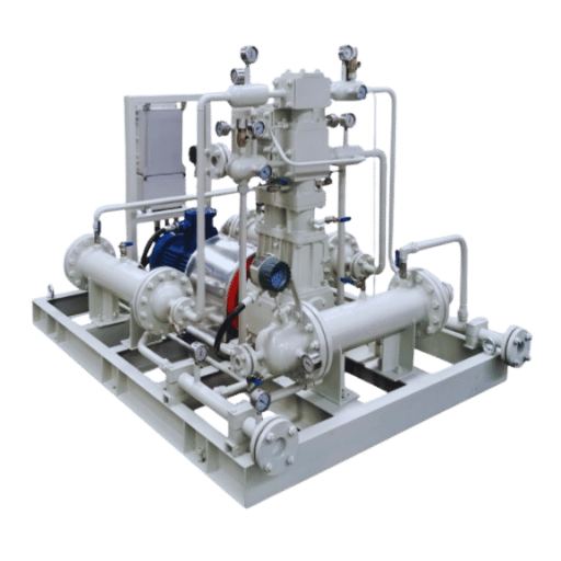
Nearly every poor compressor purchase traces back to an incomplete request-for-quote. Four parameters settle 90% of the design decision; a missing one forces vendors to guess, and the guess is usually wrong in the direction that sells more machine. The 4-Parameter Selection Framework makes the inputs explicit.
The 4-Parameter Selection Framework
- Q — Flow rate in Nm³/h at standard conditions (101.325 kPa, 0 °C), not actual cubic meters
- P₁ — Inlet pressure in MPa gauge, measured at the compressor suction flange after knockout and filters
- P₂ — Discharge pressure in MPa gauge, measured at the point-of-use (not the compressor flange — include line losses)
- X — Gas composition: methane %, C₂+ hydrocarbons, CO₂, H₂S in ppm, water content, and expected dew point
What size natural gas compressor do I need?
Sizing a natural gas booster compressor means translating the four parameters above — flow Q, inlet pressure P₁, discharge pressure P₂, and gas composition X — into a stage count, cylinder displacement, and driver power. A workable first estimate of absorbed power is P_kW ≈ Q × (P₂ − P₁) × k / η, where k is the polytropic-work coefficient (roughly 0.11 for methane at typical ratios) and η is isentropic efficiency (0.85–0.90 for modern reciprocating). A 500 Nm³/h stream moving from 0.1 MPa to 1.8 MPa through a two-stage reciprocating machine draws about 55–65 kW at the shaft, before driver derating and ambient correction. That is the envelope; final sizing depends on gas composition and duty profile.
Composition is the parameter that separates a competent selection from a misselection. H₂S above about 200 ppm (0.345 kPa partial pressure at typical suction) triggers NACE MR0175 / ISO 15156 materials requirements on wetted metallurgy, PTFE-based packing, and corrosion-resistant seals. A high-CO₂ biogas stream similarly demands stainless wetted parts and more aggressive dehydration. Missing this in the RFQ is how the “cheap” compressor becomes the expensive one — replacement of sour-service-unready cylinders costs more than the original skid.
| Inlet pressure P₁ | Discharge pressure P₂ | Recommended approach |
|---|---|---|
| 0.02–0.1 MPa (casing gas) | 1.5–2.0 MPa | 2-stage reciprocating, V-type, with upstream knockout and scrubber |
| 0.2–1.6 MPa (pipeline) | 2.0–4.2 MPa | 1- or 2-stage reciprocating, V-type, continuous duty |
| 0.2–0.4 MPa (CNG) | 20–25 MPa | Screw first stage + 3-stage reciprocating, intercooled |
| 0.5 MPa (fuel gas) | 3–5 MPa | Single-stage reciprocating or integrally geared centrifugal at 5,000+ Nm³/h |
| 0.02–0.2 MPa (biogas) | 1.6–4.5 MPa | 2- or 3-stage reciprocating with stainless wetted parts |
For a process view of booster sizing beyond natural gas, see booster selection methodology, and to run the numbers against your own Q / P₁ / P₂ combination, use the natural gas compressor sizing calculator.
What API 618, NACE MR0175, and ISO 9001 Actually Mean for Buyers
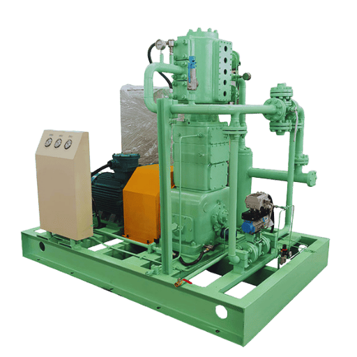
Four standards cover most of the compliance surface for a natural gas booster compressor, and the gap between “compliant” in a marketing brochure and “compliant” in an acceptance test is wide enough to drive a fully loaded skid through. Reading them in practical terms saves buyers from shipping-delay surprises and field-rework bills.
API 618 — Reciprocating Compressors for Petroleum, Chemical, and Gas Industry Services. Current edition is the 6th (2024), and it is the single most consequential document for a new reciprocating purchase. It defines the design approach (DA1, DA2, DA3) for pulsation analysis, pulsation-bottle sizing, mechanical response analysis, and — importantly — vibration acceptance limits referenced to ISO 20816-1. A 2024 PMC peer-reviewed study on pulsation elimination in a reciprocating compressor is a rare openly published example of API 618 + ISO 20816-1 acceptance in a real machine test. Ask for the vendor’s pulsation study letter, mechanical response analysis summary, and factory-test vibration certificate before signing off.
NACE MR0175 / ISO 15156 — Sour Service Materials. Threshold that matters: 0.05 psia (0.345 kPa) of H₂S partial pressure, adopted by NACE in 1978 and carried through to the current ISO 15156 harmonized standard. Above that threshold in a wet gas stream, sulfide stress cracking becomes a design concern, and cylinder metallurgy, bolting, packing, and seals must follow the sour-service materials lists. At typical suction pressures, 200 ppm H₂S is a practical working threshold for specifying NACE metallurgy.
ISO 9001 — Quality Management. Relevant because it tells you whether the vendor has a documented manufacturing process to point at, not because the certificate alone guarantees anything about the machine. Ask for the specific quality plan applicable to your order.
ASME BPVC Section VIII — Pressure Vessel Code. Applies to intercooler shells, separators, pulsation bottles, and receivers on the compressor skid. Any buyer accepting a US or EU installation needs stamped nameplates or equivalent local-code certification on pressure-containing vessels.
⚠️ Watch for “API 618 compliant” without documentation
Vendors claiming “API 618 compliant” should be able to name the design approach (DA1, DA2, or DA3), show the pulsation study report, and produce the mechanical response analysis. If any of those documents is missing from the quote package, the compliance claim is a preference, not a commitment. Same applies to NACE MR0175 — ask for the materials certification specifically for the wetted components of your order, not a generic plant-level letter.
Maintenance, Failure Modes, and the Cost of Ownership
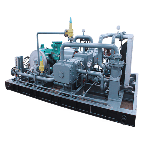
Published lifecycle cost data for industrial compressors is consistent across sources. Atlas Copco’s lifecycle cost benchmark — in line with U.S. DOE Industrial Technologies Program ranges — breaks a typical industrial compressor’s 15- to 20-year operating budget into 70% energy, 20% capital investment, and 7% maintenance and servicing. Call it the 70/20/10 Rule as a memory aid; the exact benchmark is 70/20/7 with the remaining few percent split across miscellaneous support. Practical implication: a compressor that costs 15% more up-front and delivers 5% better isentropic efficiency saves real money across its service life.
Worked example. Take a 500 Nm³/h reciprocating package priced at $75,000 with 88% isentropic efficiency versus a $65,000 package at 83% efficiency running 8,000 hours per year at $0.09/kWh over 15 years: the cheaper machine pays roughly $310,000 more in energy over that window. Capital saving evaporates inside the first two years. Same math sits behind the TCO comparison calculator that buyers use during bid evaluation.
Are natural gas booster compressors worth it?
Natural gas booster compressors are worth it when the value of recovered or moved gas, plus avoided flaring penalties, exceeds annualized total cost of ownership — which across a 15-year life is roughly 70% energy, 20% capital, and 7% maintenance. Standard casing-gas recovery packages at 400 Nm³/h pay back capital in 18 to 30 months against flared-gas revenue alone, before any methane-reduction credits. For pipeline and CNG duty where the machine is essential to operations rather than optional, the question shifts from “is it worth it” to “which efficiency band is worth paying for” — and the 5-point isentropic efficiency premium almost always is.
Failure modes ranked by frequency in reciprocating natural gas service: (1) valve wear — the dominant maintenance item, with service intervals of 4,000 to 8,000 hours per the CAGI and Chart Industries reciprocating compressor guides; (2) piston ring wear at 8,000 to 16,000 hours; (3) rod packing leakage at 2,000 to 4,000 hours; (4) unloader malfunction; (5) pulsation-induced piping fatigue where the API 618 pulsation study was skipped or underbuilt. A practitioner observation consistent across industry forums is that a large fraction of valve failures trace back to cross-mixed valve plates across cylinders during rebuild — the root cause is paperwork, not metallurgy.
One contrarian reality worth stating: Penn State Extension cites an EPA estimate that traditional reciprocating compressors account for roughly 45% of methane emissions in the U.S. natural gas transportation and storage sector. That is not a reason to abandon reciprocating technology — it is a reason to spend on proper rod-packing design, leak-detection telemetry, and scheduled packing replacement rather than stretching intervals. Maintenance budget is also the emissions budget. See reciprocating compressor maintenance fundamentals for detailed interval tables.
Frequently Asked Questions
What is a natural gas booster compressor?
View Answer
It is a secondary compression machine that takes natural gas at an elevated inlet pressure — commonly 0.02 to 4.0 MPa — and raises it to the higher discharge pressure needed downstream, such as pipeline injection, CNG storage tank filling, or turbine fuel-gas supply.
What’s the difference between a booster compressor and a primary compressor?
View Answer
Primary compressors start from near-atmospheric suction and develop the initial pressure rise — at a wellhead, for instance, or at the entrance to a gathering system. Booster compressors take gas that is already above atmospheric and add a further pressure lift. Because suction pressure is elevated, the booster runs at a smaller per-stage ratio and a lower compression temperature, so the same duty can often be handled in fewer stages with less power per Nm³/h.
Can a reciprocating booster compressor handle sour gas with H₂S?
View Answer
Yes, with proper upstream conditioning and NACE-compliant materials. NACE MR0175 / ISO 15156 treats an H₂S partial pressure of 0.05 psia (0.345 kPa) as the threshold above which sour-service design becomes required. In practical terms, for gas streams around 200 ppm H₂S at typical suction, the cylinder metallurgy, bolting, packing, and seals must follow the sour-service materials lists. A dedicated inlet scrubber and knockout drum remove free liquid, and PTFE-based packing is standard for sour duty. Provide a complete gas analysis — methane, C₂+, CO₂, H₂S in ppm, water content, dew point — at the RFQ stage so the vendor can specify the right materials rather than guess.
How much does a natural gas booster compressor cost?
View Answer
Pricing varies widely by discharge pressure and package scope. Small casing-gas reciprocating packages fall in the $8,000 to $25,000 range FOB, pipeline boosters run $25,000 to $120,000, and CNG station packages reach $80,000 to $250,000 depending on discharge pressure and throughput. More useful number is lifecycle cost: published benchmarks put energy at about 70% of total ownership cost over 15 to 20 years, with capital at 20% and maintenance at 7%. Always request kW per Nm³/h alongside quoted unit price — the cheaper nameplate is often not the cheaper machine.
What certifications should a natural gas booster compressor have?
View Answer
At minimum: API 618 (6th ed., 2024) for reciprocating design and vibration acceptance; ISO 9001 for the vendor’s quality management system; ASME BPVC Section VIII for intercoolers and pressure vessels; and NACE MR0175 / ISO 15156 for sour service if H₂S partial pressure exceeds 0.05 psia. For hazardous-area installation, add ATEX or IECEx certification on the driver, instrumentation, and controls.
How long does a reciprocating natural gas booster last?
View Answer
Frame life of 20+ years is realistic with disciplined maintenance. The CAGI and Chart Industries reciprocating compressor maintenance guides put valve service at 4,000 to 8,000 hours, piston ring replacement at 8,000 to 16,000 hours, and rod packing at 2,000 to 4,000 hours. Quarterly oil analysis to detect wear metals early and annual vibration surveys against the API 618 / ISO 20816-1 limits set by the acceptance test round out the program. Operators who follow those intervals typically see mechanical availability above 95% across the asset life; operators who stretch the valve interval past 10,000 hours typically see availability collapse inside the following year.
Related Articles
- Industrial Gas Booster Compressors — Applications and Technology Fit
- Nitrogen Booster Compressors — How They Work and How to Choose
- Hydrogen Booster Compressor Manufacturers — Technology Comparison
- Diaphragm Compressors — When a Diaphragm Beats a Piston
- How Diaphragm Compressors Work — Mechanism and Applications
- Natural Gas Compression Ratio Calculator — Stage Planning Tool
Why This Guide Exists
Most natural gas booster compressor content online reads like spec-sheet fragments stitched together. This guide is the engineering-team reference we wished we had on hand during bid reviews — compression physics, selection framework, and lifecycle math drawn from API 618 (6th ed., 2024), U.S. DOE NETL and EIA compressor data, Penn State Extension research on interstate transmission stations, and thirty years of reciprocating-compressor manufacturing practice at Pangeng’s Bengbu plant. If a specific sizing or metallurgy question is not answered here, send the gas composition and duty conditions to our engineering team directly.
References & Sources
- Understanding Natural Gas Compressor Stations — Penn State Extension
- Natural Gas Annual 2024 — U.S. Energy Information Administration
- Natural Gas Compressors and Processors — Overview and Potential Impact on Power System Reliability — U.S. Department of Energy NETL
- Vibration and Pressure Pulsation Elimination in a Reciprocating Compressor — U.S. National Library of Medicine, PMC (2024)
- API 618, Reciprocating Compressors for Petroleum, Chemical, and Gas Industry Services (6th ed., 2024) — American Petroleum Institute
- ANSI/NACE MR0175 / ISO 15156 — Petroleum and Natural Gas Industries, Materials for Use in H₂S-Containing Environments — AMPP / ISO
- A Review of the NACE Sour Limit — Evolution and Implications — NACE CORROSION 2021 proceedings
- Reciprocating Air Compressor Maintenance — Compressed Air & Gas Institute (CAGI)
- What is the Cost of a Compressor? — Lifecycle Cost Benchmark — Atlas Copco
- Impact of Electrifying Natural Gas Transmission Compression (2024) — Interstate Natural Gas Association of America
![Low Pressure Hydrogen Compressor Applications [Guide]](https://pgcompress.com/wp-content/uploads/2026/09/low-pressure-hydrogen-compressor-applications-blog-featured-150x150.png)