Get in Touch with Pangeng

PTO Air Compressor Guide: Sizing, Safety & Maintenance

Contents
show
A PTO air compressor is an air-compressor package driven by a host machine’s power take-off. This concise definition conceals the real integration task: the host, PTO, driveline, compressor, cooling path, storage, controls, treatment, and air users all must agree on a single operating condition.
This guide applies to operators, fleet teams, upfitters, and buyers who must gather defensible data before a configuration review. It explains how the system works, how to frame demand, where storage helps, which conditions call for a stop, and what evidence belongs in a maintenance or request-for-quotation record.
Scope boundary: this article does not recommend a Pangeng model or publish universal airflow, pressure, PTO speed, torque, drive ratio, duty cycle, receiver size, temperature, service interval, tool demand, or safety factor. Final compatibility and release require the exact host-machine, PTO, compressor, receiver, workplace, and jurisdictional documents.
How a PTO air compressor moves power and air
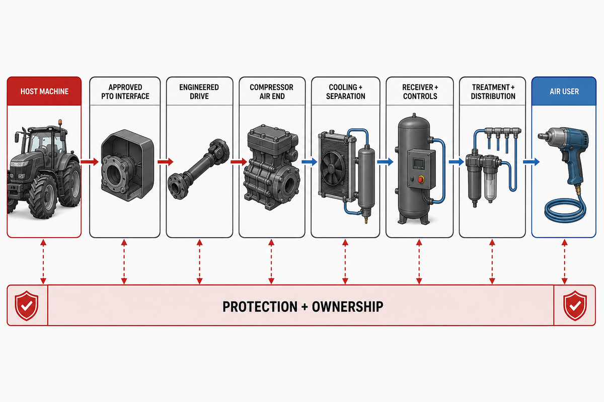
The host engine supplies mechanical power. An approved PTO interface extracts power from the vehicle transmission, tractor, or other host and transmits rotation through a direct coupling, shaft, belt, or engineered PTO drive. The compressor air end draws in atmospheric air, increases its pressure, and sends it through the package’s cooling, separation, storage, treatment, and distribution components.
“PTO air compressor” thus describes a power source and a function, but not a universal layout. Rotation, permissible input speed, steady torque, engagement transient, mounting geometry, shaft alignment, host operating condition, and unloading logic are all package-specific. A tractor-shaft model can’t be directly applied to a truck underdeck installation, nor does a competitor’s direct-mount architecture prove compatibility with another host.
| Element category | Input to collect | Evidence or transfer limit |
|---|---|---|
| Host machine | Approved operating state and available power | Host maker or responsible upfitter approval |
| PTO interface | Rotation, speed and torque envelope | Named PTO data and engagement procedure |
| Coupling or driveline | Geometry, alignment, movement and guarding | Integrator design and inspection evidence |
| Compressor air end | Permitted input and rated air conditions | Exact datasheet and manual |
| Cooling and separation | Ambient, airflow, contamination and condensate path | Installed heat-rejection and drainage check |
| Receiver and controls | Pressure band, storage event and recharge time | Rated components and approved control sequence |
| Treatment and distribution | Air-quality target, hose or pipe path and losses | Point-of-use measurement, not nameplate inference |
| Air users | Pressure, flow, duration and simultaneous use | Tool or process document plus observed duty |
| Protection and ownership | Guards, shutdowns, procedures and decision owners | Commissioning and release record |
Use the Power–Air–Heat Readiness Chain
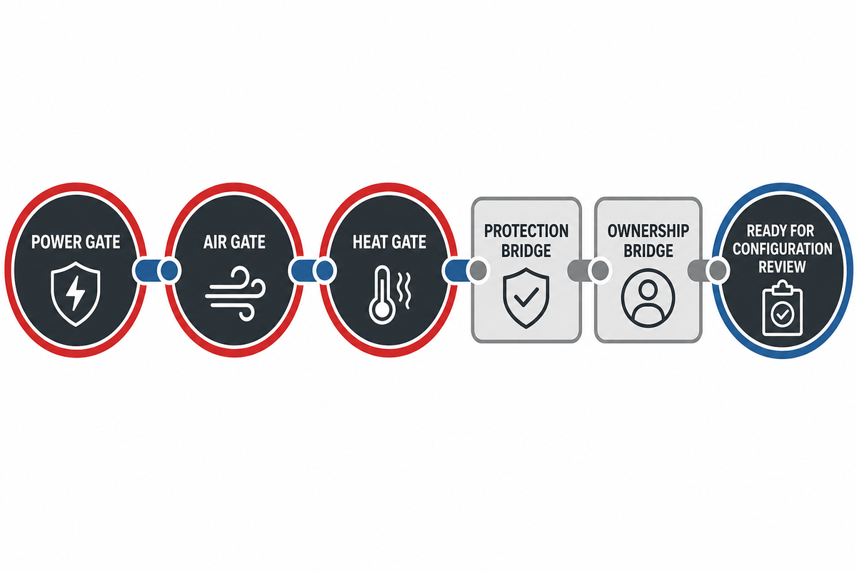
The Power–Air–Heat Readiness Chain prevents a catalog airflow number from deciding an integration by itself. Each chain link has an owner, an input, a failure signal, and an exit condition. If one link is unverified, the package is not ready for configuration review.
3-Gate Power–Air–Heat Framework
The first three links are the work gates; safety and ownership link them together. This makes the named chain usable as a review framework without pretending that a single equation can resolve mechanical fit, delivered air, and heat rejection.
- Power gate: verify approved interface, rotation, available torque and speed, engagement logic, host operating condition, and the owner who consents to the integration.
- Air gate: record simultaneous consumers, pressure at each point of use, event duration, distribution loss, treatment, moisture and condensate handling, storage, controls, and recharge time.
- Heat gate: establish ambient conditions, enclosure, cooler airflow, exhaust recirculation, dust or debris ingestion, and service clearance.
- Protection bridge: certify guards, couplings, rated hoses and components, receiver protection, alarms, controls, and shutdowns.
- Ownership bridge: identify the host approver, PTO vendor, package integrator, installer, operator, and maintenance release holder.
Exit state
The chain ends at “ready for configuration review.” It does not end with an automatic product recommendation, because the actual ratings, geometry, controls, guarding, and approvals still belong to the responsible equipment parties.
Size from the air-demand envelope
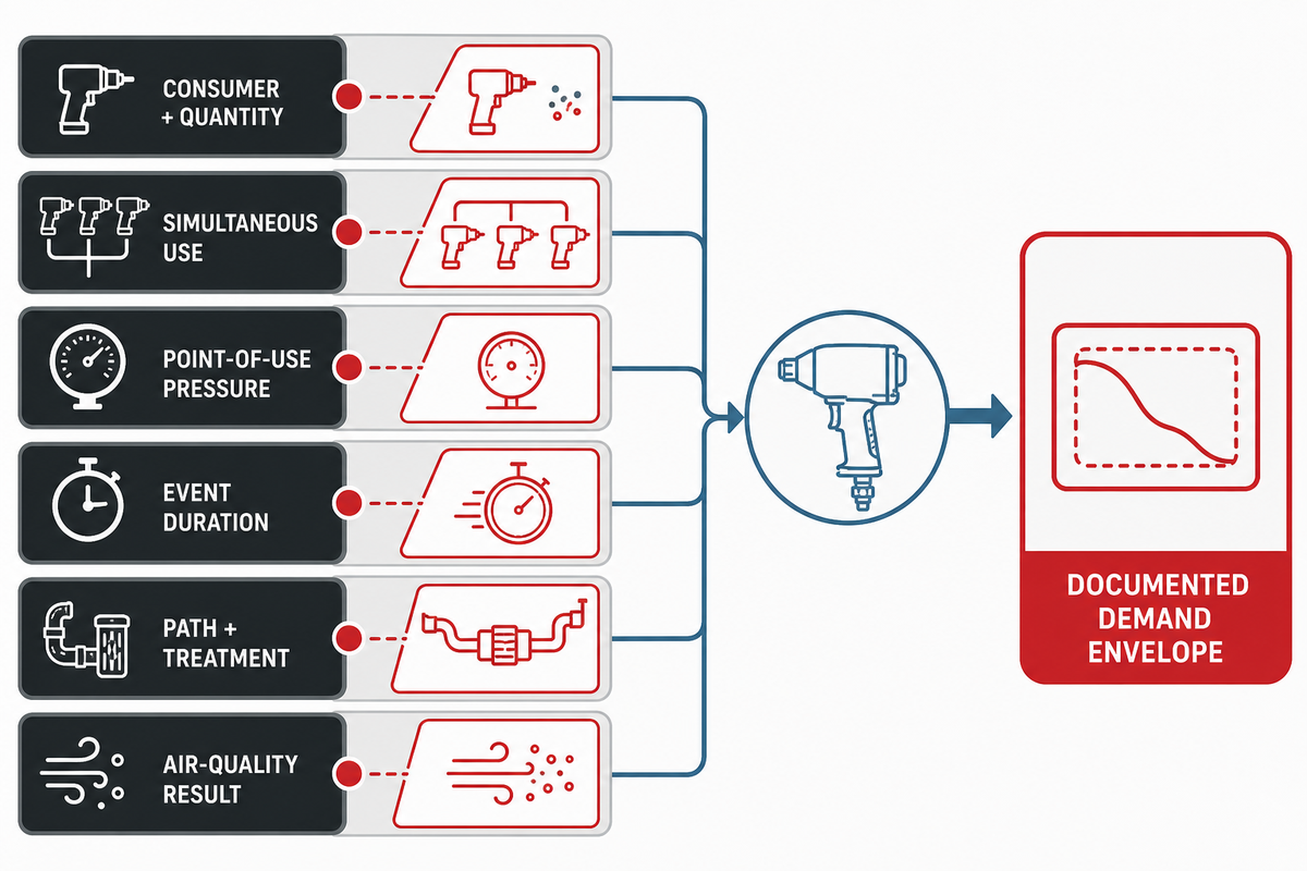
Airflow and pressure answer different questions. Flow describes a rate under stated conditions; pressure describes the condition against which the system and user operate. A CFM value is incomplete until its reference condition and measurement point are named. A compressor peak, a receiver pressure, and a tool’s point-of-use requirement cannot be compared as though they were the same quantity.
CAGI specifies demand, pressure, and air quality as the three inputs to define before equipment selection. For a PTO package, include time and location: which consumers run together, how long each takes, where pressure must be supplied, and what occurs between the compressor outlet and the user.
| Input | Question to answer | Source |
|---|---|---|
| Consumer and quantity | Which tools or processes may operate? | Tool/process document |
| Simultaneous use | Which events truly overlap? | Observed workflow |
| Point-of-use pressure | What must reach the user while flowing? | Maker requirement and test |
| Event duration | How long is a typical and longest run? | Work cycle record |
| Path and treatment | What hose, fittings, filters, dryer, or reel lies between? | Installed-system survey |
| Air quality | What moisture, particulate, or oil result is required? | Application requirement |
Do not invent a universal diversity factor or future margin. If a later demand is credible, document the event and its source. If it is only possible, label it as an unresolved scenario. For a separate discussion of rotary screw and reciprocating compressor duty patterns, use the dedicated comparison guide; the demand envelope here stays technology-neutral.
Treat receivers and controls as response tools, not free capacity
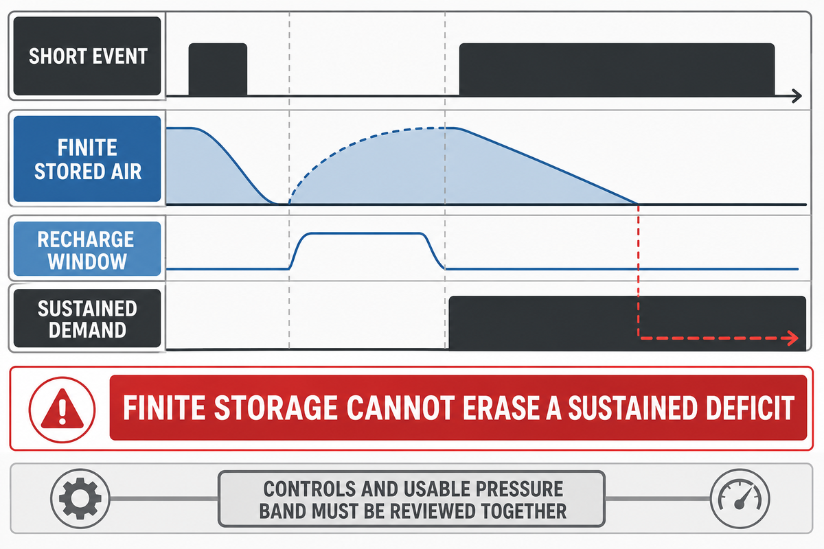
A receiver stores a finite quantity of compressed air over a usable pressure range. That storage can bridge a short or intermittent event, damp a pressure response, and interact with loading or unloading controls. It does not increase the compressor’s sustained production rate.
The source used for this method is an August 2004 Department of Energy industrial-system tip sheet. It remains useful for the relationship among variable demand, storage, controls, and recharge, but its age and stationary-system scope mean it is not current mobile-package design guidance.
The United States Department of Energy’s two-page storage guidance makes the important qualification: storage can serve temporary demand and may allow a smaller compressor in a variable-demand profile when the required air quantity, quality, controls, and recharge interval are designed together. The transferable boundary is not “storage never affects selection.”
It is “finite storage cannot erase an unbounded sustained deficit.”
Do
- Define event quantity and duration.
- Name the usable pressure band.
- Measure recovery before the next event.
- Check air quality, ratings, and control response.
Don’t
- Use a generic tank-to-flow ratio.
- Call receiver pressure usable tool pressure.
- Assume storage covers a sustained shortfall.
- Use a normal controller as overpressure protection.
If point-of-use pressure continues to fall through a long event, review actual demand, distribution loss, treatment restriction, leaks, control state, usable receiver range, recharge time, and sustained compressor delivery together. “Add a larger tank” is not a diagnosis.
Guard the driveline before discussing output
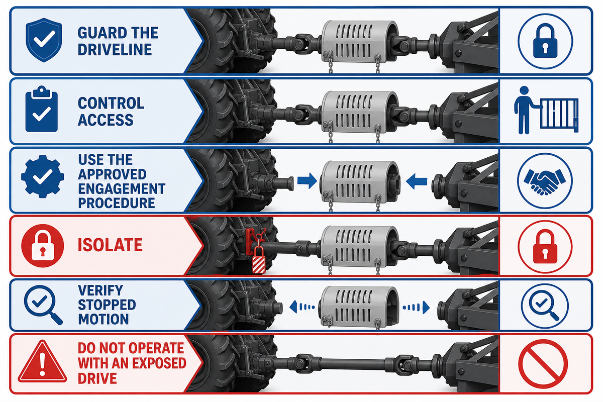
A mechanically aligned drive is not ready to operate until rotating components are guarded, access is controlled, and a safe isolation method is approved. PTO shafts, couplings, belts, pulleys, chains, keys, and other moving parts can create entanglement, contact, and unexpected-motion hazards.
OSHA 1928.57 provides an agricultural PTO example, including guarding and a bounded instruction to stop the engine, disconnect power, and wait for motion to stop before specified service. OSHA 1926.307 separately addresses mechanical power-transmission guarding in construction. These are sector-specific public examples, not interchangeable rules for every tractor, truck, shop, or road-service task.
Before operation
- Verify every required guard is present and secure.
- Confirm controlled access and the responsible operator.
- Use the approved engagement and host operating procedure.
- Stop for a damaged, missing, rubbing, or improvised guard.
Never normalize
- Reaching across a rotating shaft.
- Operating with an exposed coupling or key.
- Removing a guard for an “observation run.”
- Servicing before isolation and stopped-motion verification.
The transportation-equipment exclusion in OSHA 1910.169 is limited to that air-receiver section. It is not a general exemption from guarding, energy control, employer duties, equipment instructions, or other applicable requirements. Likewise, a host already approved to power a hydraulic pump does not prove that a compressor has the same input, mounting, cooling, control, or guarding requirements. The responsible party must determine which rules govern the actual equipment, employer, task, and location.
Control stored pressure, hoses and pneumatic tools
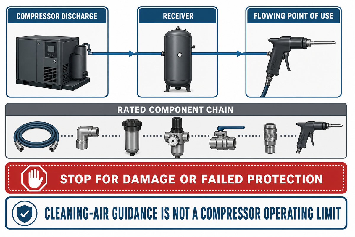
Discharge pressure, receiver pressure, and pressure at a flowing tool are separate conditions. Record where each value is measured. Then verify that the receiver, hose, fittings, couplings, reels, treatment components, valves, and tools are rated and maintained for their real service.
OSHA 1926.302 supplies construction-specific examples for positive tool-to-hose securement, manufacturer safe-pressure limits for hoses and fittings, and protection for certain hose arrangements. Its source-or-branch protection example uses a hose threshold greater than 1/2 inch inside diameter; that number stays inside the construction rule and is not a universal mobile-hose design instruction. OSHA 1910.169 gives drains, gauges, and safety-valve examples for covered air receivers but explicitly says that section is not intended to apply to compressed-air machinery on transportation vehicles such as automotive equipment. A mobile package therefore needs its actual vehicle, equipment, employer, and jurisdictional requirements—not a copied stationary checklist.
The familiar 30 psi statement is not a compressor operating limit. OSHA 1910.242(b) addresses compressed air used for cleaning and includes additional guarding and personal-protection conditions. It should not be relabeled as a receiver, discharge, or tool-supply target.
Stop for a damaged hose or coupling, an abnormal receiver condition, uncontrolled pressure, leakage that exposes personnel, missing protection, or a gauge, relief device, shutdown, or controller that does not behave as documented. Depressurize through the approved procedure; never crack a fitting or defeat a protective device to “see what happens.”
Build maintenance around conditions and failure signals
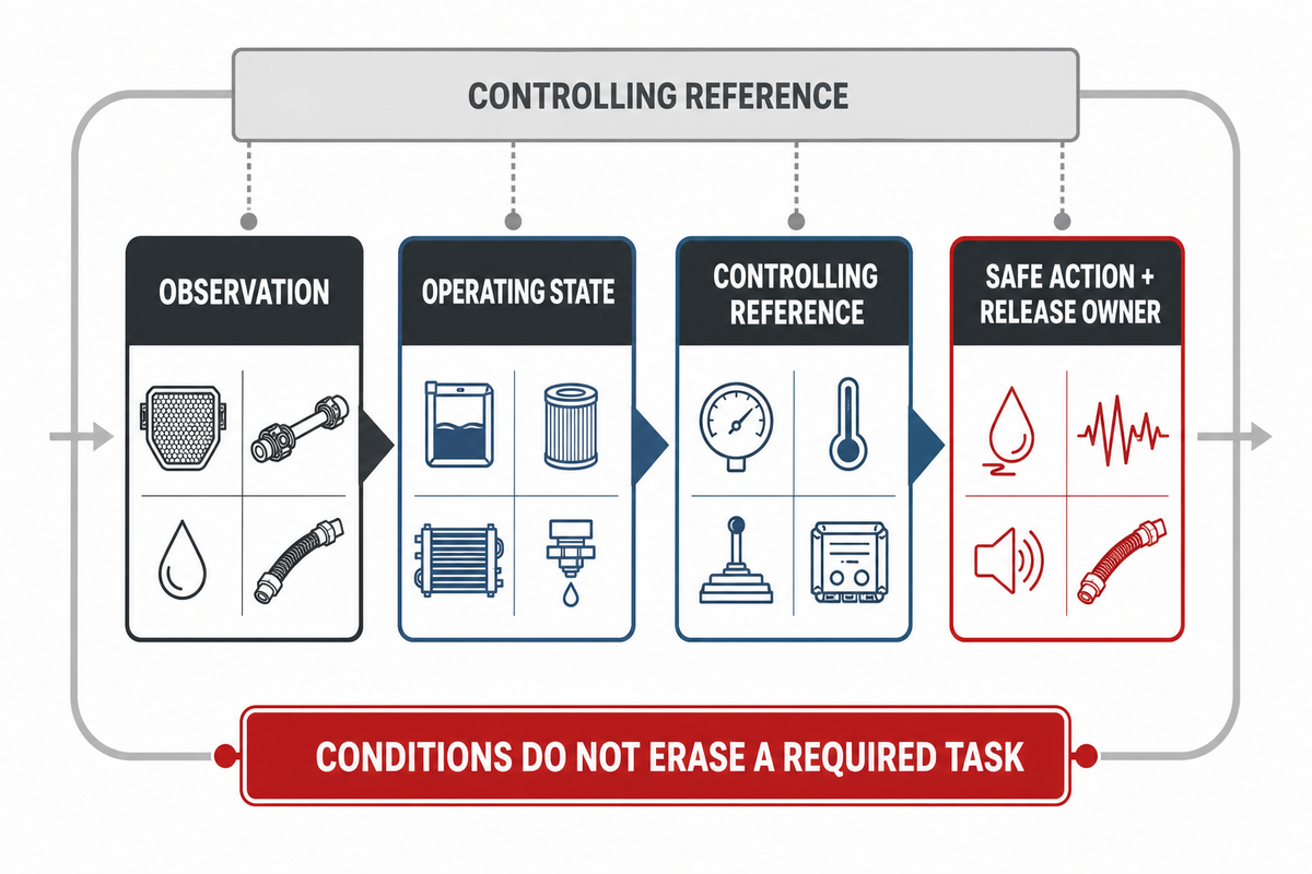
No public source in this research established one service interval or acceptable temperature for every PTO compressor package. Required intervals and limits come from the exact host-machine, PTO, compressor, receiver, treatment, and control documents. Conditions and observations help the team act within those requirements; they do not erase a required task.
| Observation | Operating state | Reference | Safe action and release |
|---|---|---|---|
| Guard, fastener, shaft or coupling condition | Before use and after relevant work | Host/PTO/integrator documents | Stop for damage; qualified release |
| Fluid, filter, cooler and drain state | Ambient, load, contamination and run time | Exact package limits and intervals | Approved service; record before/after evidence |
| Pressure, temperature and control response | Same demand event and measurement point | Commissioning baseline and manual | Escalate unexplained change; no bypass |
| Leak, vibration, noise or hose condition | Location, timing, load and recent change | Procedure and accepted baseline | Stop when unsafe; owner documents return |
Hot, dusty, wet, corrosive, restricted-airflow, or long-loaded usage might warrant closer attention or a shortened action interval, but only the team responsible for the equipment and maintenance can set it. Note the condition that prompted the action, the reference used, who did the job, and who approved the system.
Use the Three-State PTO Stoplight Check
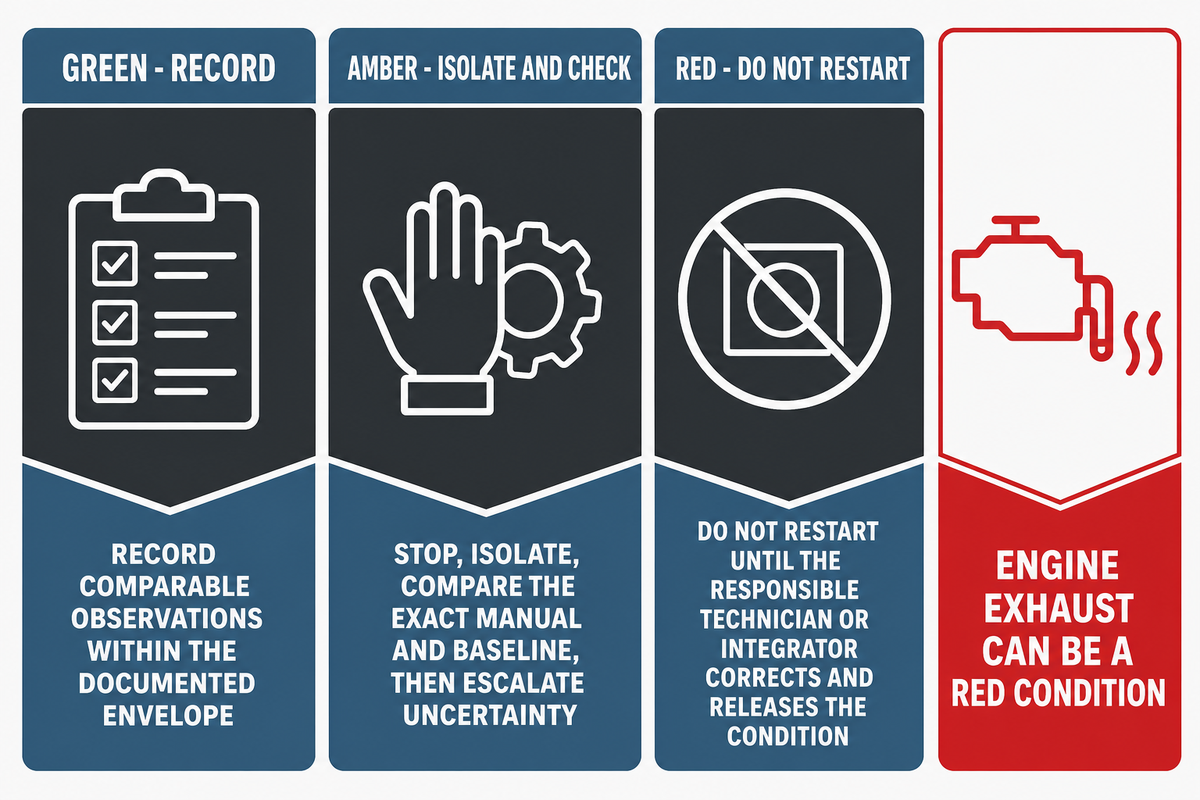
The Three-State PTO Stoplight Check separates safe observation from controlled investigation and red-stop conditions. It is a triage card, not a remote diagnostic procedure.
Green: record
Operate within the documented envelope. Record comparable pressure, temperature, control, noise, vibration, and demand observations.
Amber: isolate and check
Safely stop and isolate, compare the exact manual and baseline, and escalate when the cause or limit is unclear.
Red: do not restart
Stop, isolate, prevent use, and wait for the responsible technician or integrator to correct and release the condition.
Red examples include a missing or damaged guard; an unsafe hose or coupling; sudden severe vibration or noise; uncontrolled pressure or temperature; visible leakage that exposes people; an abnormal receiver condition; or a protective device, shutdown, gauge, loading, or unloading sequence that does not behave as documented.
Add engine exhaust to the red list. NIOSH warns that carbon monoxide can accumulate rapidly in buildings and semi-enclosed spaces and specifically advises placing gasoline-powered air-compressor power units outside and away from air intakes. The same page gives employers a 20 ft placement recommendation for gasoline engines near building openings and cites a 200 ppm NIOSH ceiling when discussing personal monitors. Those values belong to that employer guidance; they are not converted here into a universal vehicle clearance, a field-adjustment target, or a substitute for qualified exposure assessment. A stationary truck or tractor engine is also an exhaust source. Stop when exhaust could accumulate in a garage, building, or partially enclosed area, or be drawn into an occupied space. Follow the site procedure for relocation, air monitoring, emergency response, and medical help.
Common prohibited shortcuts are removing a guard for a live check, changing an unloader or protected control without authority, repeatedly resetting a trip, opening a pressurized connection, or continuing because a symptom disappeared. The return-to-service record must name the cause addressed, the approved reference, the comparable verification state, and the release owner.
Prepare a PTO Integration Brief before asking for a configuration

A request that says only “PTO compressor” transfers unanswered risk to the next party. A useful PTO Integration Brief makes each interface reviewable:
| Input | Question to close | Evidence source |
|---|---|---|
| Host identity and operating state | Which make, model, year, transmission or tractor interface, and operating state apply? | Host document and responsible upfitter approval |
| PTO input | Which location, rotation, speed range, steady torque, and engagement limits are approved? | Named PTO data and engagement procedure |
| Drive and mounting | What space, movement, alignment, and guarding concept must the integration address? | Integrator design and inspection record |
| Air consumers | Which users, quantities, and point-of-use pressures define the demand? | Tool or process documents |
| Demand timing | Which events overlap, how long do they last, and what recovery window exists? | Observed work-cycle record |
| Distribution path | Which hose, reel, piping, fittings, and treatment components affect delivery? | Installed-system survey |
| Air-quality result | What result is required, and where must it be verified? | Application requirement and test point |
| Receiver and controls | What storage event, usable pressure band, control sequence, and recharge target apply? | Rated-component data and control document |
| Heat-rejection conditions | Which ambient, altitude, dust, weather, enclosure, and cooler-airflow conditions matter? | Site survey and package limits |
| Condensate route | How will condensate be collected and disposed of where permitted? | Site procedure and applicable requirements |
| Access and protection | Which service clearances, isolation methods, alarms, and shutdowns are required? | Equipment instructions and safety review |
| Applicable requirements | Which employer, vehicle, equipment, task, and jurisdictional rules govern? | Responsible authority determination |
| Commissioning and ownership | Which measurements close acceptance, and who owns release and maintenance records? | Commissioning and handover record |
Once the brief is complete, review available PTO air compressor configurations against the collected inputs. That linked solution page owns configuration, specifications, compatibility discussion, quotation, and ordering. This guide remains the educational and evidence-preparation resource.
Frequently Asked Questions
What is a PTO compressor?
Answer
A PTO compressor is an air-compressor package that receives mechanical power through a power take-off interface on a vehicle, tractor, transmission, or other host. The term does not define one shaft, mounting, control, or protection layout. To evaluate one, identify the host operating state, PTO input, drive arrangement, compressor limits, demand, cooling, storage, controls, guarding, and responsible approval parties.
How does a PTO-driven air compressor work?
Answer
The host supplies power to an approved PTO interface, which transfers rotation through an engineered drive to the compressor. The air end compresses intake air, and the package cools, separates, stores, treats, controls, and distributes it. During engagement, mechanical input and the compressor’s current load state interact; during operation, delivered pressure depends on demand and the downstream path as well as compressor production. Rotation, speed, steady torque, engagement limits, unloading, heat rejection, and shutdown behavior all remain system-specific. Use the exact host, PTO, compressor, receiver, and control documents to define the sequence and release it for use.
Does a larger receiver increase compressor capacity?
Answer
No. A receiver stores air and can bridge a quantified short event. With a known demand quantity, usable pressure band, control response, and enough recharge time, that storage may influence production selection for variable demand. It still does not raise sustained compressor output or cover a long-running deficit. Falling pressure during a long event requires a system review rather than a tank-only conclusion.
Can a PTO air compressor run continuously?
Answer
Only if the complete host, PTO, driveline, compressor, cooling, control, and protection package is rated and released for that duty under the actual conditions. Air-end type alone does not prove continuous operation. Missing limits make the duty unverified.
What maintenance does a PTO compressor need?
Answer
Use the exact manuals to set intervals and limits. A program commonly records guards, fasteners, driveline or coupling condition, belts where fitted, fluids, filters, coolers, drains, hoses, leakage, vibration, controls, alarms, and service history. Isolate and depressurize through the approved procedure before service.
When should an operator stop a PTO compressor?
Answer
Stop for damaged guards, hoses, couplings, abnormal receiver conditions, abrupt vibration or noise, uncontrolled pressure or temperature, exposed leakage, failed protection, or exhaust that could accumulate or enter an air intake. Do not bypass a protection device to keep working.
Turn your field notes into a reviewable integration brief
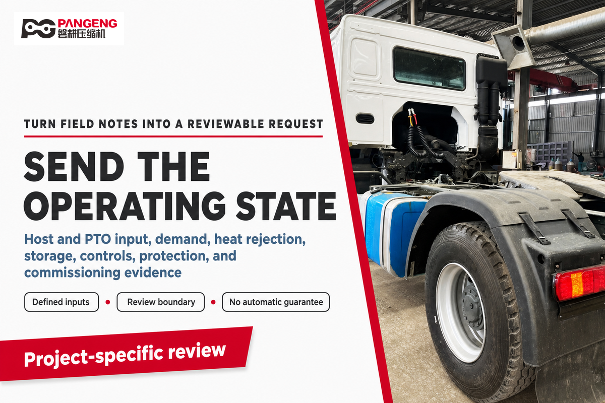
Share the host and PTO interface, demand envelope, heat-rejection conditions, storage and treatment needs, controls, safety ownership, and commissioning evidence. Pangeng can then review a project-specific configuration without treating this guide as a compatibility guarantee.
References & Sources
- OSHA 1928.57: Guarding of farm field equipment, farmstead equipment, and cotton gins
- OSHA 1926.307: Mechanical power-transmission apparatus
- OSHA 1926.302: Power-operated hand tools
- OSHA 1910.169: Air receivers
- OSHA 1910.242: Hand and portable powered tools and equipment
- NIOSH: Carbon Monoxide Hazards at Work
- United States Department of Energy: Compressed Air Storage Strategies
- Compressed Air and Gas Institute: Working with Compressed Air
- Penn State Extension: Power Take-Off Safety
- Parker Chelsea: PTO steady and transient torque context
// SYS-DOC: WHY I WRITE THIS
[01] About PanGeng
PanGeng is an industrial gas compressor manufacturer based in Bengbu, Anhui, China. Since 2009, we have focused on the design, R&D, production, and manufacturing of customized gas compressor systems for oilfield, chemical, energy, hydrogen, nitrogen, biogas, and industrial air applications.
[02] Our Expertise
We write compressor guides based on real manufacturing and engineering experience, including hydrogen compressors, nitrogen compressors, booster compressors, medium and high-pressure air compressors, oilfield nitrogen injection systems, biogas compressors, and OEM/ODM custom compressor solutions.
Our engineering team supports customers from application analysis and compressor selection to production, factory testing, commissioning, spare parts, and after-sales service.
[03] Why You Can Trust This Content
The technical information in our articles is based on PanGeng’s in-house compressor design and manufacturing experience, current product capabilities, and project support for industrial clients in global markets. Our goal is to help buyers understand compressor types, pressure ranges, gas requirements, customization options, and long-term operating costs before making a purchasing decision.
CONTACT PROFILE
AUTHORITATIVE SOURCE
NAME
PanGeng Engineering Team
BRAND
PanGeng
COUNTRY
China
MODEL
B2B / OEM & ODM
EMAIL
pg20090705@163.com
PHONE
0552-4958225
WEBSITE
pgcompress.com
Trending now


![Low Pressure Hydrogen Compressor Applications [Guide]](https://pgcompress.com/wp-content/uploads/2026/09/low-pressure-hydrogen-compressor-applications-blog-featured-150x150.png)