Get in Touch with Pangeng


Quick Specs: scope of this guide
- Duty: close a defined pressure gap between a hydrogen source and an approved destination.
- Pressure basis: absolute pressure for compression ratio; label every measurement point.
- Worked example: assumed 1.30 bar absolute suction and 1.90 bar absolute discharge, giving a 0.60 bar lift.
- Selection inputs: flow, gas condition, operating cases, controls and downstream acceptance.
Hydrogen supply can be close to the pressure needed by a process and still not be sufficient. Between the hydrogen supply and the process, a dryer or delivery line may consume the available pressure difference. Also, the source pressure may change. Low pressure hydrogen compressor applications are determined by the boundaries of the process; that is, where the gas is taken and where it’s delivered. Applications of hydrogen are presented in this report according to the boundaries of the process.
Low pressure hydrogen compressor applications include boosting local process supply, hydrogen recovery and re-circulating gas if a real pressure shortage is confirmed. The proposed hydrogen compressor may not be sufficient for the required process flow, and gas quality and responsiveness may limit equipment usage.
Key points
- An electrolyzer that already meets the downstream pressure requirement may need no additional compressor.
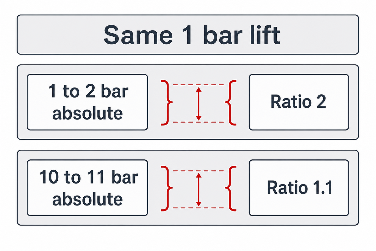
- A 1 bar lift from 1 to 2 bar absolute has a ratio of 2; the same lift from 10 to 11 bar absolute has a ratio of 1.1.
- Wet fuel-cell return loops require a dedicated circulation assessment.
- A quotation should cover changing demand and treatment energy as well as a steady-state duty point.
Updated September 2026. All numerical pressure budgets presented here are illustrative assumptions, not Pangeng performance data or equipment ratings.
What low pressure means in hydrogen compression
Low pressure is a process condition. Compressor equipment may have a low pressure inlet. Its duty may still involve high compression. Compact package size and a small pressure lift are independent characteristics. These characteristics shouldn’t define one product category. Specify hydrogen flow, gas condition, suction and discharge pressure for each operating case.
The U.S. Department of Energy defines compression ratio as outlet pressure divided by inlet pressure, so a compressor with a low pressure inlet can still have a high compression ratio. Just stating that equipment is “low pressure” gives very little information to the buyer.
For a pressure ratio, divide discharge absolute pressure by suction absolute pressure. OpenStax explains the relationship between gauge and absolute pressure: absolute pressure includes the local atmospheric reference. Gauge values can’t simply be divided to obtain a compression ratio.
In an assumed comparison, increasing pressure from 1 bar absolute to 2 bar absolute doubles the absolute pressure. Moving from 10 bar absolute to 11 bar absolute increases it by one tenth. Both duties add 1 bar, yet their ratios are 2 and 1.1. These ratios alone cannot determine a machine’s motor rating; flow, temperature, gas properties and the actual application also matter.
When a supplier gives you a smaller machine to correspond with a smaller lift, request that the machine be balanced on the same basis as your process balance, i.e. on an inlet-flow basis. The size of the compressor can’t be determined from knowledge of the pressure lift alone. Our hydrogen gas compressor selection checks cover more detailed equipment specifications.
Different compressors, including any compressor for hydrogen, are assessed for suitability to perform their proposed pressure duties. The high pressure ratio duty doesn’t perform the same function as a low ratio pressure duty. Similarly, a low ratio pressure duty doesn’t perform the same function as a high ratio pressure duty. It’s also incorrect to compare hydrogen technologies by package size alone.
Where a small pressure lift earns its place

The candidate pressure duties include local supply, recovery and circulation of hydrogen gas. Each of the above-mentioned duties requires a defined receiving pressure and gas specification, and the gas condition is significant; an application name alone does not establish equipment suitability.
Application Interface Ledger
An Application Interface Ledger describes the source, destination, acceptance condition and justification for considering the use of a pressure-raising device.
This matrix is based on reviewed sources and includes screening questions. Approved equipment assignments aren’t provided. Important differences in the interfaces described in DOE’s integration webinar, Enapter’s handbook and the fuel-cell literature are included in the matrix.
| Interface | Pressure-lift question | Acceptance condition / limitation |
|---|---|---|
| Electrolyzer to local user | Does available outlet pressure cover delivery losses? | Compare the electrolyzer envelope with the user’s minimum inlet requirement. |
| Dryer outlet to process header | Does treatment consume the available pressure gap? | Use documented treatment loss at the relevant flow; check gas quality separately. |
| Buffer to intermittent test bench | Can supply meet demand as buffer pressure changes? | Specify minimum source pressure, peak demand and cycling duty. |
| Qualified recovered gas to reuse header | Is a usable return destination above the source pressure? | Confirm composition and treatment acceptance before evaluating compression. |
| Wet anode return to fuel-cell inlet | What circulation pressure and flow does the stack require? | Assess water, mixed gases, load range and stack-specific controls. |
| Fresh feed to ejector motive inlet | Is motive pressure available across the operating range? | Check entrainment at low load; an ejector does not create its own pressure energy. |
| Pilot source to changing experimental load | Can supply follow the experiment’s demand changes? | Agree pressure excursions and recovery time with both equipment providers. |
| Plant supply to upstream storage stage | Is the small lift only one stage of a larger system? | Evaluate the full compressor train and storage boundary. |
| Supply to vehicle refueling storage | Does the final duty require high pressure? | Treat refueling and storage as a separate system-selection problem. |
Within a hydrogen infrastructure, it’s possible to have a low pressure connection and still not define the entire system. For example, hydrogen fueling stations, also called hydrogen refueling stations, may have separate hydrogen connections for storage and supply. A low-pressure storage connection may also exist in the hydrogen transfer system, but fuel-cell supply differs from stack recirculation and refueling service. In either case, suitability of an upstream transfer connection does not establish suitability for the final hydrogen refueling system.
Hydrogen compressors are used in facilities that transport and store hydrogen; a pressure budget describes the pressure required for each transfer. The role of hydrogen in the receiving process determines the facility’s acceptance specification. Transfer of liquid hydrogen is outside the scope of this gas-pressure analysis, and equipment for that duty can’t be selected using this pressure budget.
A screening example with a 1.60 bar absolute receiving requirement and a 1.30 bar absolute source already has a pressure gap before delivery losses. It may be appropriate to use a compressor in this case; however, this should be determined by an analysis of the complete interface.
Electrolyzer outlets and local hydrogen supply
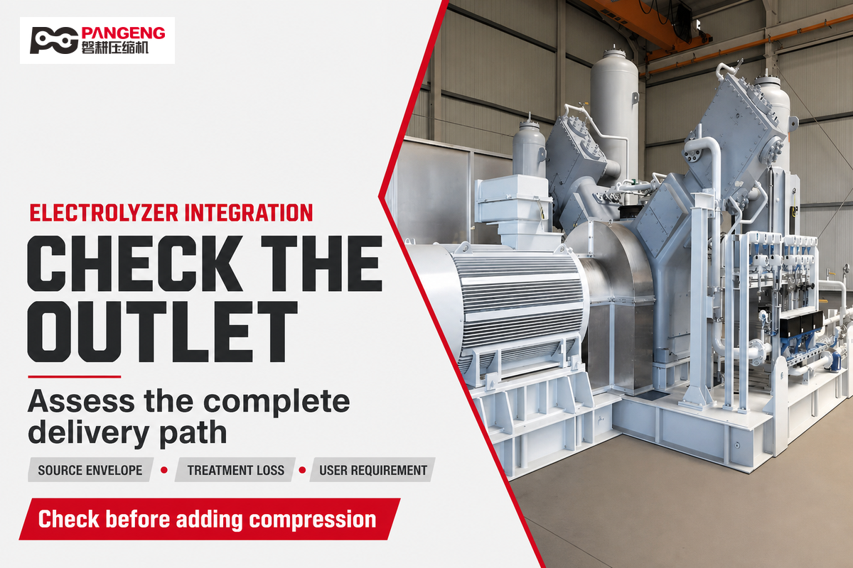
Some electrolyzers may require boosting to provide the required pressure to downstream users. Other electrolyzers may provide a pressurized hydrogen connection. Pressure connections for hydrogen should be analyzed along with the complete system.
When can an electrolyzer supply hydrogen without a compressor?
An electrolyzer can supply a local user without additional compression when its approved outlet envelope satisfies the user’s pressure, flow and quality requirements. The system providers must confirm that determination for the complete delivery path. Removing protective equipment or adjusting operating settings is outside this comparison; the system designers must confirm the approved operating envelope.
The example provided in the Enapter technical integration handbook demonstrates product-specific pre-compressed output and separate drying considerations. Its stated 35 bar gauge output condition is a feature of the documented equipment, not a pressure available from every electrolyzer. Pressurization of output doesn’t prove that it meets the downstream user’s acceptance specification.
“the type of electrolyzer used has a significant impact on the compressor selection.”
In the DOE ARIES System Webinar, Daniel Leighton described system control as consisting of three layers: device controllers, hydrogen-system supervision and plant control. They assessed dynamic operation of the electrolyzer by measuring outlet mass flow and utilizing internal-pressure behavioral patterns while tuning operation with the system supplier.
Prior to authorizing capital expenditures, confirm that both suppliers have agreed on which of them controls delivery pressure and what happens to the pressure during a change in demand. The steady outlet value won’t address these questions. The requested integration should include the dryer, downstream process, cooling and utility systems.
The need for hydrogen compression should be based on the expected system demands downstream and not on the presence of an electrolyzer. If the existing system already provides the required pressure, an additional system should be justified. If the existing system doesn’t, the system should be integrated in a manner that increases the pressure of hydrogen without exceeding the operating limits of the system.
Enapter’s documented 35 bar gauge condition illustrates why an extra booster isn’t automatically required after electrolysis. Just because electrolysis is part of the project, it doesn’t mean a booster is required. Electrolysis does not neutralize pressure; how much pressure is available and lost is a case-by-case matter and must be assessed by the supplier for the specific equipment.
Recovering hydrogen for a usable return destination
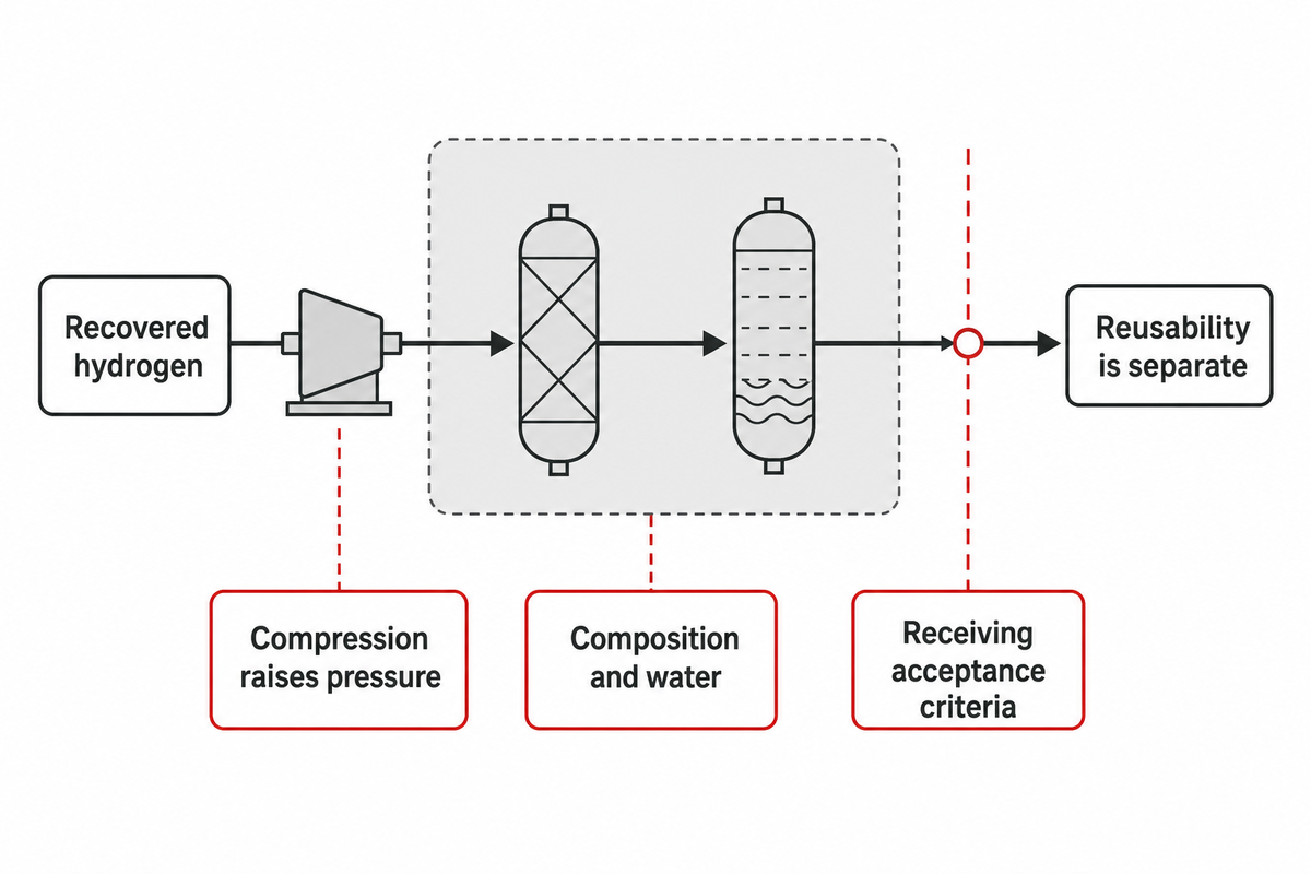
Hydrogen that’s recovered must have an acceptable return destination to justify spending on hydrogen recovery. Hydrogen recovered from a stream at the stated pressure must be of acceptable quality for the system that receives the gas. Compression can move a stream, but does not establish that a contaminated stream is reusable.
A recovery destination may be unusable if composition or water falls outside the receiving header’s acceptance criteria. Document the concentration of hydrogen, water, and relevant impurities. Don’t use “pure hydrogen” to label the stream. It isn’t appropriate to make assumptions about the composition of the stream. Recovered gas in a stream may contain constituents that compromise the equipment and/or process. Description of the source may require detailed composition.
A review in CompressorTech2, by Timothy Ablondi and Mark Barton, shows how unspecified gas and operating assumptions can change a proposed package. Its historical cost and power illustrations aren’t used here. The useful lesson is to obtain comparable assumptions before treating a cheaper quotation as better value.
Recovering hydrogen to an approved local header is different from transporting hydrogen or storing hydrogen in a high pressure bank. A high pressure bank requires a higher pressure duty for storage of hydrogen and creates a new receiving limit. Our refinery hydrogen recycle guide describes processes and limits of hydrogen recycle and reuse in a refinery. The limits defined in the guide shouldn’t be extended to a different application, like a fuel cell.
The pressure budget should cover the pressure loss of gas conditioning. The hypothetical 0.15 bar treatment drop consumes one quarter of the example’s 0.60 bar total lift. Treatment capacity and recovery yield cannot be evaluated based on that pressure-loss-to-lift ratio.
Circulation loops: compressor, blower or ejector?
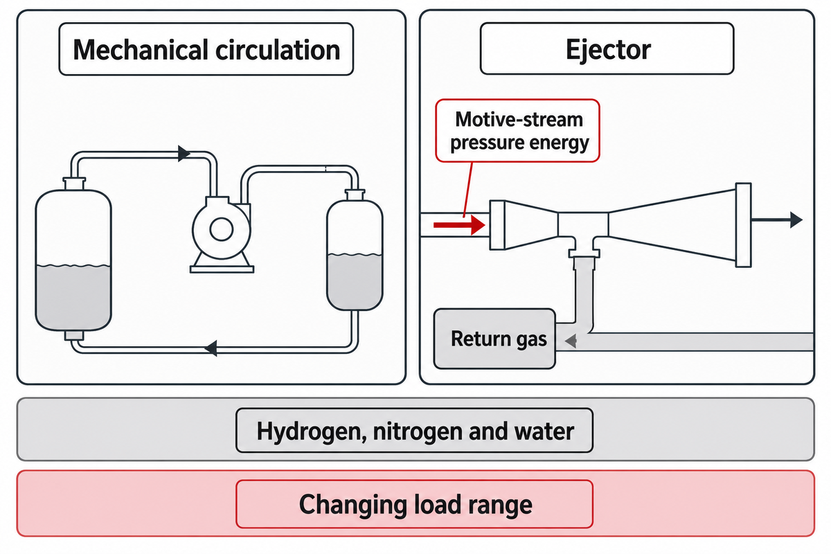
Gas circulation is evaluated based on return-gas conditions and the demand range of the process. Fuel-cell anode return gas may contain hydrogen, nitrogen, water vapor or liquid water; as this guide’s procurement recommendation, have the stack supplier assess the relevant membrane electrode assembly (MEA) conditions. For gas circulation, a blower/pump or an ejector may be used. The plant hydrogen gas compressor can’t be assigned to a fuel cell plant’s circulation duty from the difference in pressure alone.
Does a hydrogen circulation loop need a compressor?
The hydrogen circulation loop must have a means of meeting its circulation requirements. This can be a mechanical means or an ejector. Feng and colleagues’ 2023 review of fuel-cell ejector design describes both approaches and explains the difficulty of maintaining entrainment over a changing load range. These challenges are discussed in Feng’s 2023 ejector review.
An ejector uses pressure energy from a motive stream to draw in return gas. The University of Delaware’s ejector research describes that principle and contamination concerns associated with moist hydrogen circulation. Its model-validation work used air-similarity experiments; it isn’t certification of an automotive hydrogen device.
For a hydrogen fuel cell, return-gas water handling, the stack supplier’s control requirements and process variations should be considered across the operating conditions. The constraints should include the behavior of the system at off-design conditions.
Hydrogen mobility is beyond the scope of this industrial guide and requires approved vehicle-level integration of the system for fuel cell electric vehicles.
Laboratories and pilot plants with intermittent demand
Laboratory and pilot plant work can involve intermittent hydrogen usage and peak flow rates. Compact hydrogen packages can be convenient; a small hydrogen compressor still needs assessment because size doesn’t define suitability for a given experiment. Quote minimum and peak demand for hydrogen and state the source pressure. Indicate the required flow conditions and the destination conditions for delivery.
State the location of the hydrogen flow measurement. Also state if flow is expressed in terms of volume or mass and if so, in what units. If a normalized flow value is provided, state its reference pressure and temperature. Compressor systems may quote hydrogen flow on different bases to perform a function; however, different flow bases may describe different duties.
Transient conditions govern the use of hydrogen and may vary significantly during the course of an experiment. Therefore, the average flow for the case shouldn’t govern the selection of the case but the transient conditions of each case should govern. The supplier should be contacted to evaluate the case rather than averaging conditions over a number of cases.
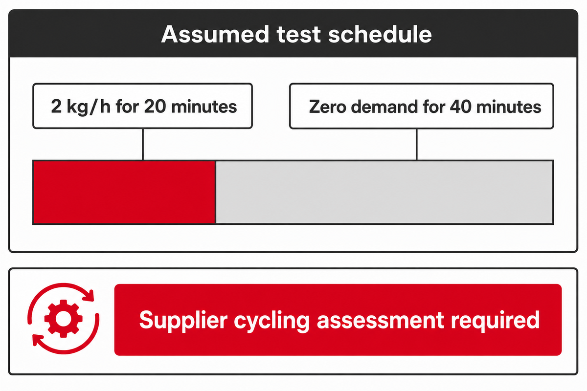
In an assumed test schedule, the process demands 2 kg/h for 20 minutes and has zero process demand for the following 40 minutes. These assumed values illustrate a planning format; they do not establish that a system is designed for the anticipated duty. The supplier must analyze the effect that the resulting start-stop or turndown duty will have on the proposed design of the compressor.
The Turbomachinery International application review discusses how changing hydrogen duties influence technology choices. Buyers should request a documented operating envelope and control proposal rather than assuming equipment for large-scale hydrogen production remains appropriate after being scaled down.
The pilot request stating 2 kg/h without the 20-minute demand period leaves an important operating condition unresolved. Adding the 40-minute idle period lets the supplier examine cycling, standby power and restart behavior. It’s recommended that all operating conditions of the process be specified prior to the equipment being evaluated.
Build a Hydrogen Pressure-Gap Budget
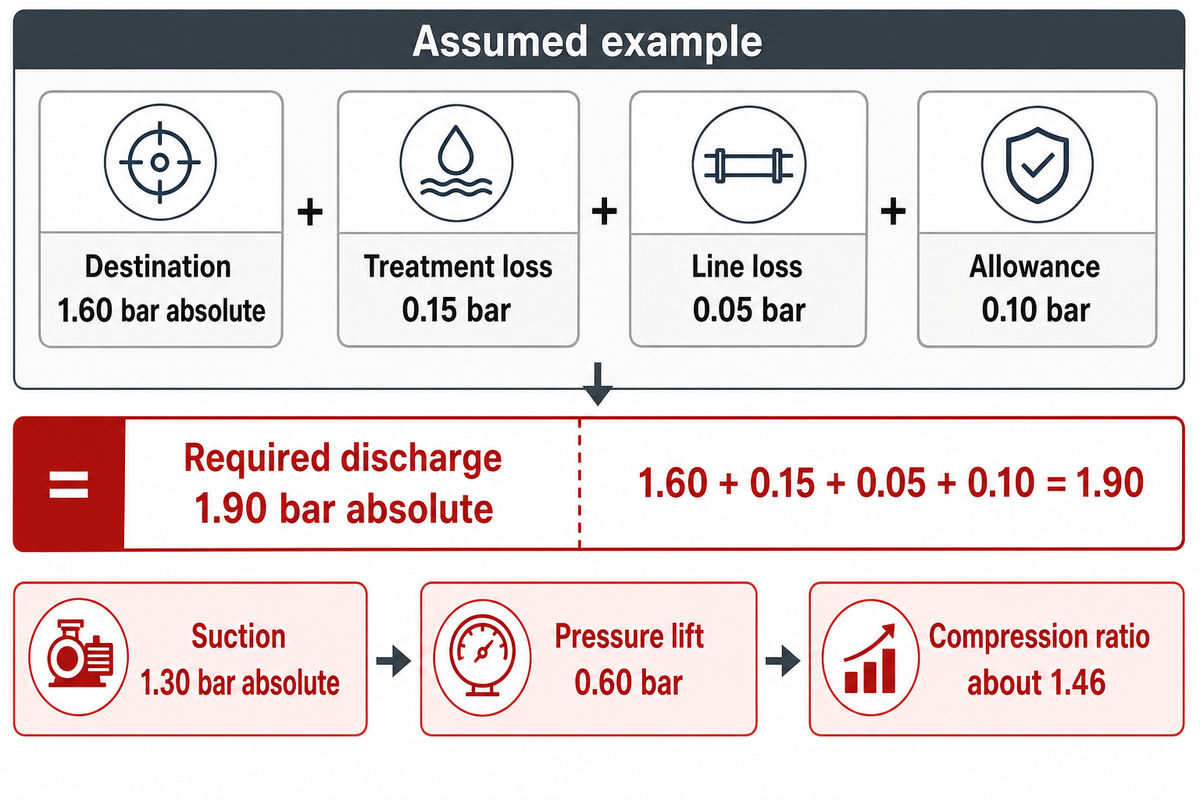
A Hydrogen Pressure-Gap Budget is a means to illustrate the receiving pressure requirement and downstream losses, and compare the resulting discharge requirement with compressor-inlet pressure. It’s a static screening tool, rather than proof of equipment suitability for the service; flow, gas condition, dynamic response and operating limitations still need assessment.
A Hydrogen Pressure-Gap Budget compares the receiving pressure plus downstream losses with pressure at the compressor inlet. It’s assumed that all pressure values refer to the same condition. Values are absolute pressures.
In this illustrative example, it’s assumed that all pressures use the same absolute-pressure basis. The source pressure value represents conditions at the compressor suction connection. Any upstream loss in the system is already reflected at the compressor inlet and isn’t to be counted again in this example.
| Quantity | Assumed value / result | Boundary or calculation |
|---|---|---|
| Destination requirement | 1.60 bar absolute | At the user’s inlet |
| Treatment pressure drop | 0.15 bar | Downstream of compressor in this assumed layout |
| Delivery-line pressure drop | 0.05 bar | At the example’s unspecified design flow |
| Chosen case allowance | 0.10 bar | Illustrative assumption; no universal margin recommended |
| Required discharge pressure | 1.90 bar absolute | 1.60 + 0.15 + 0.05 + 0.10 |
| Base suction pressure | 1.30 bar absolute | At compressor inlet; upstream losses already accounted for |
| Base pressure lift | 0.60 bar | 1.90 − 1.30 |
| Base compression ratio | Approximately 1.46 | 1.90 / 1.30, both absolute |
| Lower-source case | 1.10 bar absolute suction; 0.80 bar lift | Same assumed 1.90 bar absolute discharge; ratio approximately 1.73 |
| Higher-source case | 1.50 bar absolute suction; 0.40 bar lift | Same assumed 1.90 bar absolute discharge; ratio approximately 1.27 |
The calculation is: required discharge = destination pressure + downstream losses + the chosen case allowance. Substituting the assumptions gives 1.60 + 0.15 + 0.05 + 0.10 = 1.90 bar absolute. Subtracting 1.30 bar absolute suction gives a 0.60 bar lift. Dividing 1.90 by 1.30 gives a ratio of about 1.46.
Steady pressure balances can’t predict transient undershoots. To predict undershoots, one must determine how long it takes the system to respond (settle) to a change in demand. Record the source pressure trace and demand pattern, then ask the supplier to provide expected pressure excursions and settling time. The assumed 0.10 bar allowance isn’t proof that those excursions are covered.
Key takeaway
The illustrative 1.30-to-1.90 bar absolute duty closes a 0.60 bar static gap. It does not determine motor power, compressor capacity or dynamic delivery performance.
Gas quality, utilities and hydrogen-service safeguards
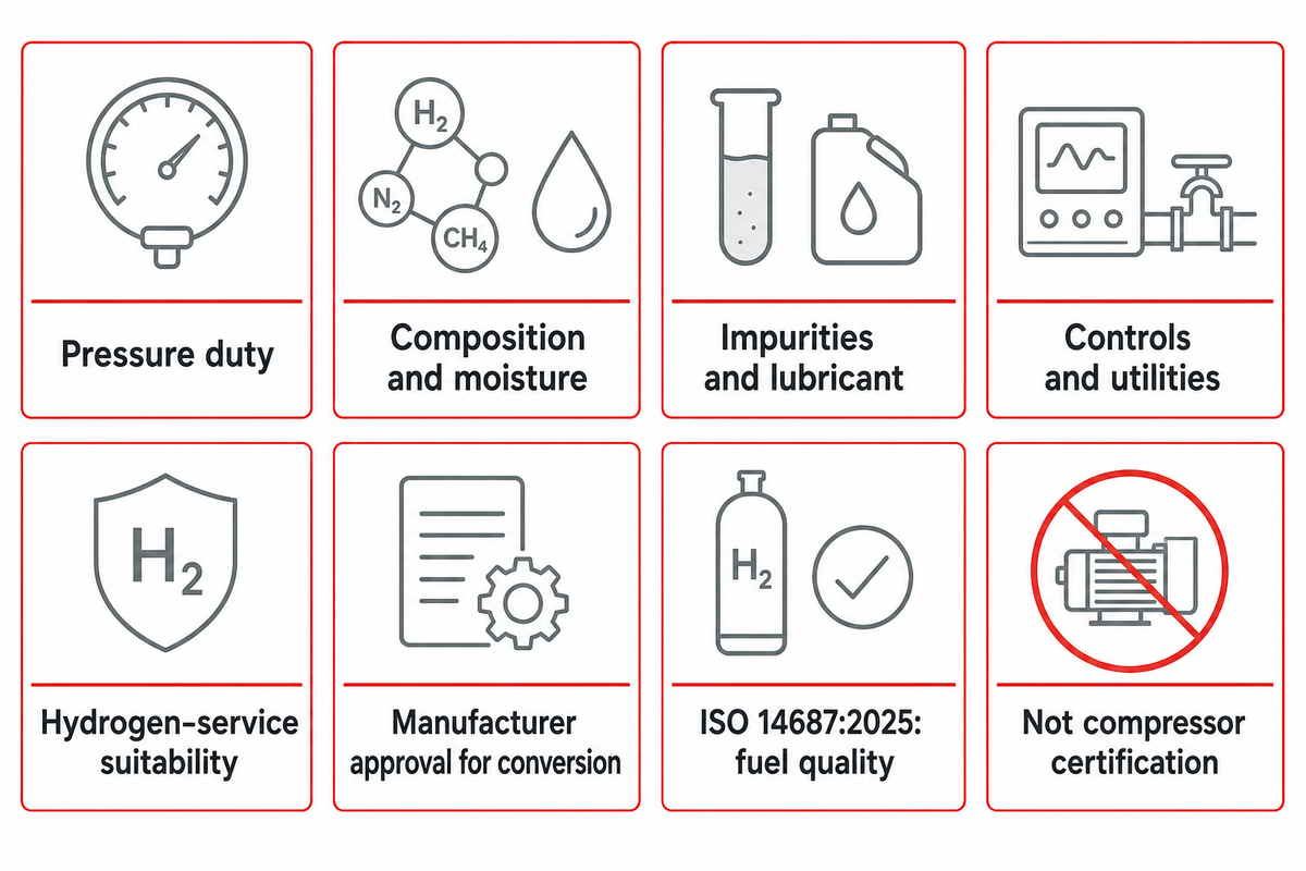
When the pressure service lift is small, one must also demonstrate suitability of the hydrogen service. One must also address type and quantity of contaminants, lubricant and other process impurities and specify process controls and utility services.
Ordinary mechanical gas compression raises pressure; it does not by itself prove hydrogen purity. The ISO catalogue lists ISO 14687:2025 as the current published hydrogen fuel quality specification. Its existence does not mean every industrial hydrogen application uses the same quality category, or that a compressor is certified against it.
Some hydrogen compression technology uses electrochemical processes with separation methods. We evaluate that technology separately. For details on the electrochemical process, refer to our electrochemical hydrogen compressor guide. Don’t attribute a purification function to a mechanical booster.
Regarding reciprocating compressors or diaphragm compressors, request reference documentation on gas-path suitability and downstream acceptance. Merely including oil-free wording doesn’t address the full impurity specification. The diaphragm hydrogen compressor overview gives pertinent information for the discussion on the technology.
Equipment used in hydrogen services includes supply, recovery and circulation. The impurity requirement for the recovery service may differ from plant to plant. Therefore, the impurity specification must be defined and the method for verifying the specification be agreed upon, prior to the acceptance of general purity language.
The H2Tools compressor FAQ specifically advises obtaining manufacturer approval before considering conversion of a nitrogen compressor to hydrogen. Similar-looking natural gas or inert-gas equipment isn’t evidence of approved hydrogen service. Material compatibility, seals, controls and accumulation risks still require the appropriate engineering assessment.
Do
- State moisture and impurity acceptance at the user’s boundary.
- Confirm the proposed package’s hydrogen-service approval.
- Include cooling, drying and control utilities in the scope.
Don’t
- Infer purity from discharge pressure.
- Substitute an inert-gas compressor without provider approval.
- Assign an unspecified allowance as a safety limit.
For the illustrative budget, a 0.15 bar drying-stage pressure drop is an assumed pressure input, not an estimate of drying performance. The treatment outlet specification and the means for the treatment and control of that specification are required. Quoting the pressure drop doesn’t confirm the drying capacity or the energy required to provide that service.
Compare quotations on the same operating cases
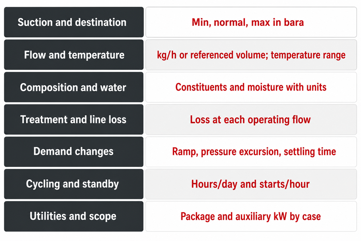
Procurement cannot compare quotes unless they use identical source conditions, receiving requirements and operating cases. Obtain from each source the equipment and control components associated with the requirement. Also, obtain the acceptance criteria. Quotes can vary based on the type and extent of work performed, integration and adjustment.
Each hydrogen compressor manufacturer should receive the same duty sheet as all other bidders. Each bid should state the scope of their proposal, limitations and its relationship to the requirement statement to allow for an informed assessment of another option, if warranted.
Siemens Energy’s hydrogen compressor intake questions separately request pressure, temperature, gas composition, water, cooling, oil carryover and control philosophy. Those distinctions remain useful when evaluating another manufacturer’s proposal. They’re Siemens’ published questions, not Pangeng test results.
The following is a checklist. “Recommended Range” is the process variable value that the buyer has to disclose. Limits aren’t provided here and therefore must be declared by the buyer, not assumed to be wide open.
Common quotation cases: inputs to declare
| Parameter | Recommended range | Why it matters | How to verify |
|---|---|---|---|
| Suction / destination | Declare min / normal / max in bara | Defines lift and ratio at named boundaries | Process data and agreed duty sheet |
| Flow / temperature | Declare kg/h or referenced volume; °C range | Sets capacity basis and gas condition | Provider performance assessment |
| Composition / water | Declare constituents and moisture in stated units | Controls compatibility and acceptance | Source analysis and receiving specification |
| Treatment / line loss | Declare bar loss at each operating flow | Prevents missing or double-counted losses | Treatment and piping design basis |
| Demand changes | Declare ramp, bar excursion and settling time in s | Exposes dynamic delivery limits | Agreed control-response evidence |
| Cycling / standby | Declare hours/day and starts/hour | Sets intermittent duty and operating cost | Schedule and supplier duty approval |
| Utilities / scope | Request package and auxiliary kW by case | Includes drying, cooling and controls | Itemized power and scope schedule |
Process engineers can review process interfaces with this information. Exclusion and lead time information can be evaluated by procurement. Operators can assess process control responsibility and access for service. Quality teams need evidence of acceptance for the given impurity specification. Energy and maintenance costs on equivalent utilization basis need to be considered before choosing a smaller machine.
The Hydrogen Tech World technology review emphasizes application-dependent choices. For a reciprocating compressor package, ask what treatment and auxiliary loads are included. Many compressors use different mechanical arrangements to compress the gas; increasing its pressure is only part of the complete installation’s energy balance.
In the worked example, changing suction from 1.30 bar absolute to 1.10 bar absolute raises the required lift from 0.60 bar to 0.80 bar at the same 1.90 bar absolute discharge. Quoting only the first case leaves the second unassessed. Ask for both cases without assigning an unsupported motor-power estimate.
Frequently asked questions
At what pressure is the gas being provided to the compressor?
Use pressure measured at the compressor inlet, with its reference basis stated, and report minimum, normal and maximum conditions so the supplier can assess the declared duty.
Give the minimum, normal and maximum suction conditions for the intended duty. State whether each value is gauge or absolute, and identify the measurement point. Pressure at an upstream vessel may differ from pressure at the compressor connection because the intervening path has losses. The inlet value should already reflect those losses, so the discharge budget must not count them again.
What is the gas composition and is there water in the gas?
Specify the actual hydrogen stream and its moisture condition.
Identify the constituents relevant to the source, equipment and receiving process. Report whether water is vapor, liquid or both across the declared operating cases. Electrolysis produces hydrogen and oxygen in separate process paths, but an outlet description still needs the supplier’s stated impurity and moisture conditions. Gas analysis and downstream acceptance are separate from the pressure-lift calculation.
What discharge pressure is required?
The discharge requirement must cover the receiving pressure and the downstream delivery path, including documented treatment and line losses at the relevant flow and an explicitly justified operating-case allowance.
Add documented treatment and line losses at the relevant flow, with any chosen allowance explicitly justified for the operating case. Then compare that requirement with suction pressure. In the assumed example, 1.60 bar absolute at the user plus 0.15 bar treatment loss, 0.05 bar line loss and a 0.10 bar illustrative allowance gives 1.90 bar absolute discharge. It isn’t a universal setting.
What happens if you compress hydrogen?
Compression raises the pressure of hydrogen gas.
Mechanical equipment compresses the hydrogen into a smaller volume or otherwise transfers energy to raise its pressure. Temperature and power depend on the process. A pressure increase doesn’t establish gas purity or permission to use the resulting stream.
Does a low-pressure hydrogen gas boost compressor exist for fuel cell vehicle applications?
Pressure-raising devices exist, but a vehicle application must identify the specific circuit and approved duty because fresh hydrogen supply, wet anode circulation and refueling involve different conditions and integration requirements.
A fuel cell vehicle can involve hydrogen supply to the stack and a separate anode-return circulation task. Those interfaces have different gas conditions and control requirements. Wet anode return can contain water and other gases, and its demand changes with stack load. A mechanical circulation pump or an ejector therefore needs dedicated assessment by the relevant providers.
Hydrogen refueling, high pressure hydrogen storage and dispensing are separate high-pressure applications. A compact industrial booster shouldn’t be treated as an approved vehicle component or refueling machine because its pressure lift sounds similar. Specify the circuit, load range, return-gas condition and acceptance evidence first. The research discussed here concerns selection principles; it doesn’t certify equipment for mobility applications.
Reliable hydrogen delivery is made possible by the joint specification of an end-user requirement. The conditions at the beginning and end of the system, the type and purity of the gas and the operating cycle have to be defined for a preliminary discussion. Evaluate the proposed equipment scope in relation to the interface ledger and pressure-gap budget. A more detailed discussion on the various items of equipment is available in our hydrogen compressor system selection guide.
Discuss your hydrogen pressure gap
Share the operating cases and receiving specification so the proposed compression package can be assessed against your process.
About the manufacturer: Anhui PanGeng Gas Compressor Co., Ltd. provides industrial gas compressor packages. This guide uses public engineering sources and declared arithmetic assumptions. It reports no Pangeng field-test results, customer savings or third-party product approvals.
References & Sources
- Gaseous Hydrogen Compression U.S. Department of Energy.
- Gauge Pressure, Absolute Pressure, and Pressure Measurement OpenStax, Rice University.
- ARIES Flatirons Campus MW-Scale Hydrogen System Research U.S. Department of Energy webinar transcript.
- Compressors are hydrogen colour-blind CompressorTech2, Timothy Ablondi and Mark Barton.
- Designing Hydrogen Recirculation Ejectors for Proton Exchange Membrane Fuel Cell Systems Feng and colleagues, Energies, 2023.
- Variable Flow-Rate Ejectors for PEMFC Anode Recirculation University of Delaware research group.
- Hydrogen Compression: Prospects & Challenges Turbomachinery International.
- ISO 14687:2025, Hydrogen fuel quality International Organization for Standardization catalogue.
- Compressors FAQ H2Tools, Pacific Northwest National Laboratory.
- Compressors and turboexpander solutions through the hydrogen value chain Hydrogen Tech World, Baker Hughes authors.



![Low Pressure Hydrogen Compressor Applications [Guide]](https://pgcompress.com/wp-content/uploads/2026/09/low-pressure-hydrogen-compressor-applications-blog-featured-150x150.png)