Get in Touch with Pangeng

Diaphragm Compressor Applications: Hydrogen, Specialty Gas, and Leak-Free Duty Guide

Contents
show
Diaphragm compressor applications are best defined by what the gas must never contact, where leakage would matter, and how much pressure ratio the process needs, not by gas name or discharge pressure alone. This guide turns those constraints into a practical selection and acceptance method.
Updated July 2026
Direct answer
Choose a diaphragm compressor when oil-free gas, strong process isolation, high compression ratio, or hazardous-gas containment outweigh high-flow economics. Then verify the entire package, not only the compressor head.
Quick specifications to collect before selection
| Gas | Composition, impurities, phase, toxicity, flammability, corrosivity and required outlet purity |
| Pressure | Minimum/normal/maximum suction and required discharge pressure at the package boundary |
| Capacity | Normal flow, peak flow, turndown, operating hours, starts per day and future expansion |
| Containment | Allowable leakage, detection method, vent destination, purge philosophy and trip response |
| Acceptance | Performance point, test gas, leak-test boundary, alarm/trip proof, certificates and witness requirements |
TL;DR
- A diaphragm isolates the process gas from the hydraulic drive, supporting clean and consequence-sensitive service.
- “Leak-free” describes a designed and tested containment target; valves, fittings, relief devices and vents remain separate package boundaries.
- Hydrogen pressure alone doesn’t choose the compressor. Suction pressure, flow, compression ratio, purity, duty cycle and availability all matter.
- Specify the end-use purity requirement and gas-specific compatibility review instead of asking for generic “high purity” construction.
- Put performance, leakage, detector function and documentation into the purchase order as acceptance criteria.
Which Applications Actually Need a Diaphragm Compressor?
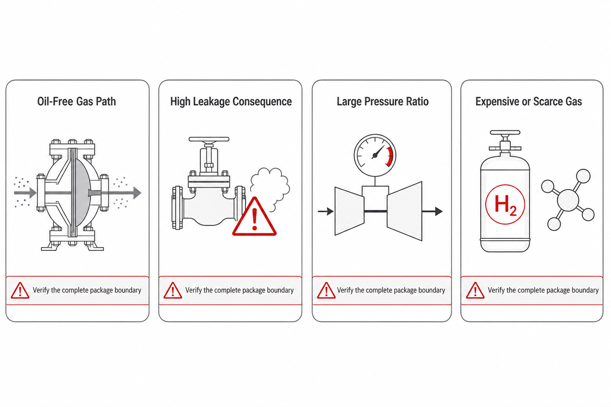
A diaphragm compressor becomes a serious candidate when one or more consequences dominate the project: lubricant carryover could spoil the gas, external leakage could create a safety or emissions problem, process gas must stay separated from the drive system, or a modest flow must be raised through a large pressure ratio. This kind of gas compressor is selected around consequence and duty, not a catalog label.
That makes the technology relevant to hydrogen compression, high-value gas recovery, analytical and calibration-gas service, toxic or flammable process duties, and applications where contamination is costlier than the compressor itself. Similar logic can apply to helium, argon, nitrogen and process mixtures, but the gas name is only the start of the specification.
The first selection test isn’t “Can a diaphragm compressor reach the pressure?” It’s “What’s the controlling loss if we choose the wrong compressor?” The loss may be contaminated product, fugitive emissions, a hazardous release, excessive parallel-machine count, or unacceptable downtime.
The DOE hydrogen-compression overview gives a useful example of that boundary: high ratio can favor reciprocating machinery, while high-throughput pipeline service can favor centrifugal equipment.
| Trigger | Why diaphragm may fit | What can still disqualify it |
|---|---|---|
| Oil-free gas path | The metallic diaphragm separates gas from the hydraulic drive | Downstream contamination sources or an unsuitable end-use purity plan |
| High leakage consequence | Static containment around the compression chamber and monitored diaphragm layers | Unspecified valves, fittings, relief seats, vents or detector response |
| Large pressure ratio | Positive-displacement operation can suit high-ratio duty | Flow, stage temperatures, suction variability or availability requirements |
| Expensive or scarce gas | Containment and recovery can reduce product loss | Recovery economics may not justify the package complexity |
Why the Diaphragm Changes the Duty Envelope
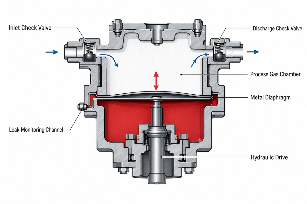
In a hydraulic diaphragm compressor, a moving metal membrane changes the gas-chamber volume while keeping the process gas apart from the hydraulic mechanism. Check valves control inlet and discharge flow. Multi-layer diaphragm arrangements can route a membrane failure signal to a monitoring channel before process gas and hydraulic fluid mix.
This architecture removes a major contamination route, but it doesn’t repeal basic compressor engineering. Diaphragm stress, pulsation, check-valve behavior, cooling, hydraulic control, suction conditions and stage ratio still shape capacity and reliability. For background, see our guide to hydrogen booster compressor selection, where inlet pressure and final duty are treated as separate inputs.
A 2026 Manufacturing Review study by Mikhail Solovev and colleagues reported that its optimized hydroformed test diaphragm exceeded five million cycles and produced 60% more displaced volume than the study’s conventional flat membrane. That’s useful engineering evidence about forming and fatigue. It isn’t a warranty for every alloy, head geometry, operating point or commercial package.
Engineering implication: diaphragm material, forming history and cyclic loading belong in the reliability discussion. Material alone does not prove service life.
Across industrial applications, the advantages of diaphragm compressors come from how a diaphragm gas compressor separates the process chamber from the hydraulic system. Static seals around the head avoid the dynamic packing used by piston machinery; in a multilayer design, a middle diaphragm can route a leak signal while the outer layers preserve separation. This does not make the compression process maintenance-free: hydraulic fluid condition, check valves, the cooling system and diaphragm fatigue life still control reliability during gas compression.
Compressing hydrogen for hydrogen refueling is one application. Petrochemical gas mixtures, rare gases, and explosive and toxic streams create different compatibility requirements. Safe operation depends on a gas-specific control system, verified materials and a defined shutdown response.
Do
- Define the gas-side containment boundary
- Specify detector alarm and trip behavior
- Ask for diaphragm, valve and seal maintenance assumptions
Don’t
- Treat a cycle-test result as package availability
- Assume every fitting is covered by “hermetic head”
- Select metallurgy from gas name alone
The 3-Bottleneck Pressure, Purity–Risk Map
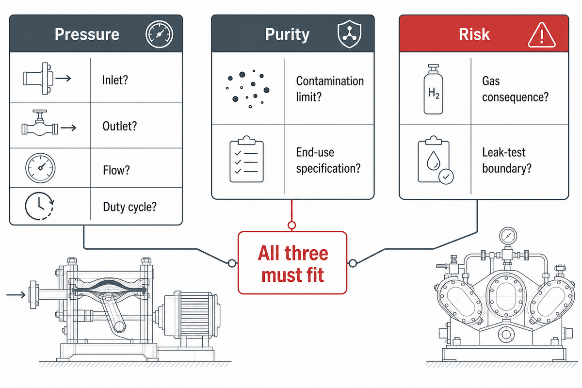
The 3-Bottleneck Pressure, Purity–Risk Map is a first-pass screen that identifies which constraint makes the compressor decision irreversible. It’s deliberately not a sizing calculation. Use it to decide what evidence must control the request for quotation.
| Bottleneck | Question | Evidence to demand |
|---|---|---|
| Pressure | What are minimum suction, maximum discharge and stage ratios? | Guaranteed points across the stated suction range; discharge-temperature and relief basis |
| Purity | Which downstream impurity specification must the gas meet? | Named end-use specification, sampling point, cleaning record and material/cleanliness certificates |
| Risk | What happens if gas escapes, mixes, ignites or is lost? | Leak-test method and boundary, detector proof, vent route, shutdown matrix and hazardous-area basis |
After the first-pass screen, add the operating envelope: minimum and normal suction pressure, ambient and cooling-medium limits, starts per day, turndown, normal and peak flow, continuous or intermittent duty, planned maintenance window, spare strategy and required availability. These variables can reverse a choice that looked obvious on pressure and purity alone.
For hydrogen projects, pair the map with the current project-scope check on the official ISO 19880-1 page; a station standard cannot be assumed to cover every industrial gas installation.
As an example, a clean, high-ratio duty at moderate flow may point toward a diaphragm design. If the process instead needs very high continuous throughput, broad turndown, short maintenance windows and high station availability, multiple diaphragm units may cost more and expose more maintenance points than a different compression train.
Key takeaway
Use pressure, purity and risk to find the bottleneck; use the full operating envelope and availability target to select and size the machine.
Hydrogen Applications: From Electrolyzer Discharge to Refueling
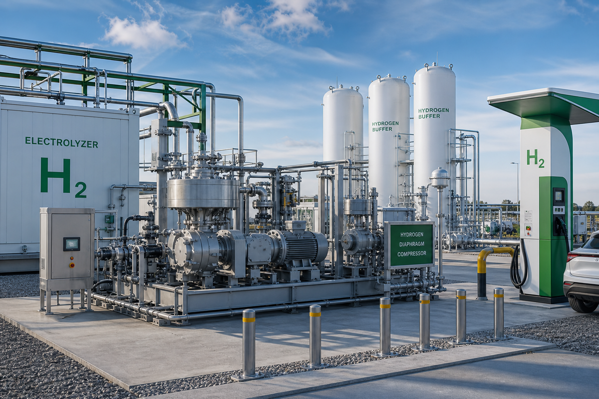
Hydrogen service isn’t one duty point. The U.S. Department of Energy notes that hydrogen is commonly produced around 20 bar to 30 bar (about 2 MPa to 3 MPa) and then compressed for transport, storage or use. A low-pressure electrolyzer outlet, a storage cascade, a tube-trailer loading line and a vehicle-fuelling station can therefore have different suction ranges, final pressures, flow patterns and redundancy needs.
Electrolyzer and production boosting
At an electrolyzer outlet, purity protection and suction variability often matter as much as the final pressure. Water carryover, start-stop behavior and low-load operation should be defined upstream of the compressor. As one first-party example, not a general market limit, PanGeng lists model DW-5.8/(0.2-0.8)-30 at 500 normal m³/h, with a 0.02 MPa minimum and 0.08 MPa maximum inlet (about 0.2 bar to 0.8 bar) and 3.0 MPa (30 bar) discharge in its hydrogen compressor model table.
Storage, transfer and cylinder filling
Storage and filling systems need the lowest credible suction pressure, maximum receiver pressure, cycle frequency and filling profile. Simply asking to “compress to 300 bar” omits the changing pressure ratio and time-at-load that influence staging, heat rejection and capacity. A practical system view appears in the gas booster hydrogen bottle-filling guide.
Fuelling stations
Hydrogen-fuelling applications add protocol, buffer storage, dispenser and station-control requirements. The official ISO 19880-1:2020 page scopes the standard to gaseous-hydrogen fuelling stations and shows that the published edition entered “to be revised” status on January 20, 2026. That lifecycle status is a reason to verify the adopted project edition; it does not turn ISO 19880-1 into a universal diaphragm-compressor standard.
ISO 19880-1 is also not a shortcut for laboratories, chemical plants, cryogenic hydrogen or metal-hydride systems outside its stated scope. Identify the facility type and jurisdiction first. Then list the applicable station, piping, electrical and end-use purity requirements in the project specification.
Recovery and test service
Hydrogen recovery, component testing and fuel-cell research may favor small or variable flows where gas value, purity and containment dominate. These projects still need a clear normal operating point. Selecting only for the highest test pressure may leave the compressor operating poorly through most of the cycle.
A named project reported by Gasworld used a diaphragm system to raise hydrogen from 30 bar (3 MPa) to 250 bar–300 bar (25 MPa–30 MPa) for underground storage. Treat that as a real application example, not a reusable sizing ratio.
Specialty and High-Purity Gas Applications
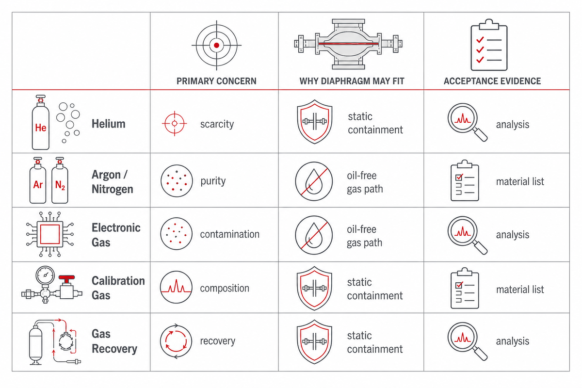
Specialty-gas service often values cleanliness, inventory retention and batch integrity more than lowest capital cost per unit of flow. Typical candidates include helium recovery, argon transfer, calibration-gas preparation, analytical gases, high-purity nitrogen and rare process gases.
With helium, the business case may be loss prevention and recovery. Calibration mixtures put composition integrity in control. In electronics or analytical service, the required impurity ceiling and sampling boundary can dominate. With argon or nitrogen, a diaphragm unit can make sense where purity and containment are critical, but a different oil-free technology may be more economical when flow is high and pressure ratio is modest.
The 2026 metal-membrane study also identifies high-purity, toxic, reactive and explosive gases as relevant duties, while showing why diaphragm material state and cyclic loading still need a project-specific review. To understand upstream nitrogen-system behavior, compare PSA and membrane nitrogen generation before sizing the compressor.
“High purity” is too vague for a purchase order. State the downstream use, required analysis, sampling location, allowable particulate and moisture limits, and whether the compressor must arrive cleaned, dried and capped. If nitrogen is part of the process, existing nitrogen-compressor specifications provide a starting point for discussing pressure and capacity.
| Gas/duty | Likely decision driver | RFQ evidence |
|---|---|---|
| Helium recovery | Product value and loss prevention | Recovery flow profile, allowable leakage and vent/recycle destination |
| Calibration mixtures | Composition integrity | Wetted-material list, cleaning method and analysis boundary |
| High-purity argon/nitrogen | Oil-free path versus flow economics | Purity requirement, flow range and alternative-compressor comparison |
| Rare or expensive gas | Inventory conservation | Expected annual loss, recovery plan and lifecycle-cost model |
Toxic, Corrosive, Flammable, and Oxygen-Rich Duties
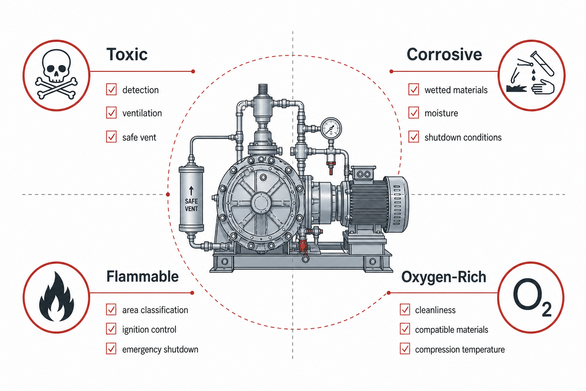
A wrong material or boundary decision can create a leak, contamination event or failed acceptance test at 3 MPa. PanGeng therefore treats gas composition, abnormal cases and the factory test boundary as linked procurement evidence rather than separate checklist items.
These services share a need for disciplined containment, but they don’t share one material or cleaning answer.
- Toxic gas: release consequence, detector location, ventilation, purge and safe vent handling control the package boundary.
- Corrosive gas: the complete wetted-material and elastomer list must be checked against composition, moisture, temperature and shutdown conditions. Corrosion allowances don’t solve every localized mechanism.
- Flammable gas: hazardous-area classification, ignition-source control, ventilation, gas detection and emergency shutdown must align with the site design.
- Oxygen-rich service: cleanliness, compatible materials, ignition mechanisms and compression temperature require an oxygen-specific review. A generic stainless-steel statement isn’t an approval.
Don’t accept “316 stainless steel” as a complete compatibility answer. Each request for quotation should identify every wetted metal, coating, gasket, valve material and cleaning condition. Ask which abnormal cases were reviewed: wet gas, air ingress, loss of cooling, blocked discharge, low suction, rapid restart and diaphragm alarm.
Scope must extend beyond the core machine. Purge panels, analyzers, vents, relief discharge and the plant tie-in can decide whether the installed system meets the hazard-control intent. Package review should therefore involve the site’s process-safety and electrical teams instead of treating the compressor as an isolated pressure machine.
For hydrogen installations specifically, the recent compression and station-safety review connects compressor selection with relief, interlocks, material suitability and piping. Its hydrogen scope shouldn’t be generalized to unrelated gases.
Diaphragm vs Piston or Screw: Where It Is Not the Best Fit
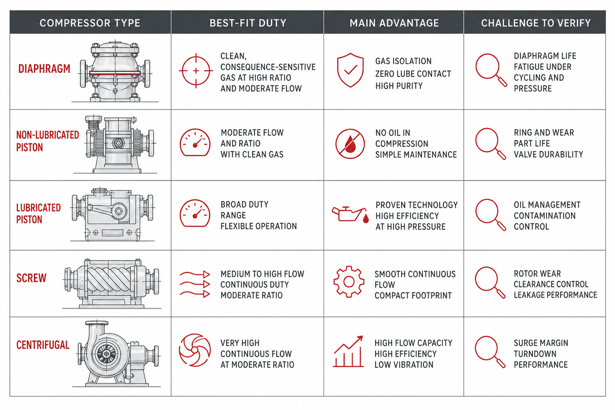
The DOE hydrogen overview supplies the most useful counterweight to blanket sales claims: reciprocating compressors, piston or diaphragm machines, are common for very high compression ratios, while centrifugal compressors are suited to high-throughput pipeline service at more moderate ratios. Pressure alone isn’t the selection rule, and an air compressor comparison can’t substitute for gas-specific engineering.
| Compressor type | Often attractive when | Challenge to check |
|---|---|---|
| Diaphragm | Clean, consequence-sensitive gas; high ratio; moderate flow | Capacity per unit, diaphragm/check-valve maintenance, cooling and parallel-unit economics |
| Non-lubricated piston | Higher flow, broad operating range or staged compression | Packing leakage, wear, contamination limit and maintenance interval |
| Lubricated piston | High-duty mechanical service where downstream separation is acceptable | Oil carryover, separation performance and end-use purity |
| Screw | Steady, lower-ratio service with suitable gas and cleanliness requirements | Final pressure, sealing method and any lubricant/separation system |
| Centrifugal | Very high continuous flow and moderate ratio | Low molecular weight, stage ratio, surge range and minimum stable flow |
| Hydraulic intensifier | Intermittent final-pressure boosting | Pulsation, cycling rate, seals, contamination and energy at the real profile |
| Electrochemical | Hydrogen-only purity and low-flow niches | Stack life, feed-gas quality, maturity and service support |
| Metal hydride | Hydrogen-only, thermally integrated low-flow duty | Heat source/sink, cycling, mass, response and commercial scale |
| Ionic liquid | Selected hydrogen-refuelling duty where a commercial package is proven | Supplier track record, liquid management, turndown and lifecycle evidence |
PanGeng’s reciprocating and diaphragm hydrogen-compressor examples illustrate why a supplier should compare architectures against one duty sheet. Where alternative hydrogen technologies are being considered, a general hydrogen-compressor overview can frame the discussion, but the guaranteed operating points must remain project-specific.
When screw or centrifugal equipment remains in the shortlist, review their basic operating envelopes. Air-service examples aren’t hydrogen ratings, but they clarify the mechanical and control questions that must be re-qualified for process gas.
A fair commercial comparison includes the number of machines, spare philosophy, maintenance labor, energy across the real load profile, cooling demand, consumables, expected product loss and cost of downtime. “Oil-free” and “high pressure” are attributes, not a lifecycle-cost model.
Normalize capacity claims before comparing quotations. One vendor-specific range reviewed during research spanned 50 psi to 15,000 psi and roughly 1 m³/h to 2,000 m³/h at normal conditions; those figures show how broad a catalog can be, not what one head or one project can deliver. Likewise, “continuous” should be defined: 24 hours/day and 365 days/year is a different availability obligation from an intermittent filling cycle.
That vendor’s project examples included a 113 kW syngas unit raising 10 bar to 30 bar and a 7.5 kW argon package raising 34 bar to 488 bar. These are useful comparison prompts, not design baselines: different gases, flows and package configurations make the numbers non-transferable.
System Integration: The Compressor Is Not the Whole Containment Boundary
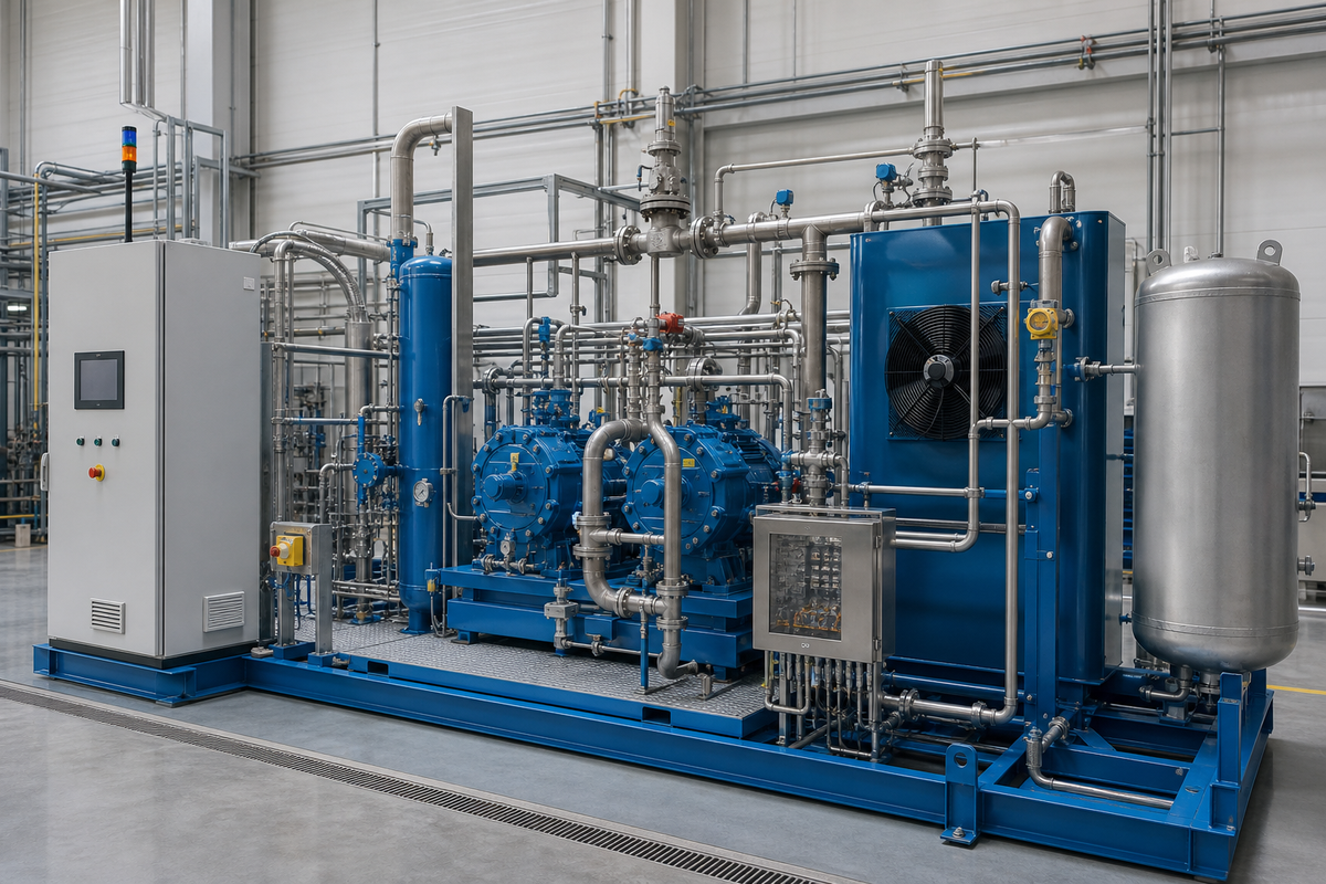
A diaphragm head can keep the process gas separated from the hydraulic drive while the package still contains potential leakage points: suction and discharge valves, instrument fittings, pressure transmitters, relief devices, drains, purge connections, vent headers, coolers and site tie-ins.
This distinction is central to leak-free duty. Define at least three boundaries:
- Process chamber boundary: gas head, diaphragm layers and local seals.
- Compressor package boundary: all factory-supplied piping, valves, instruments, relief and vent connections.
- Installed system boundary: field joints, utilities, storage, downstream isolation and vent destination.
Patent WO2022002326A1 describes separate process-side and hydraulic-side leakage paths with monitored pressure and shutdown logic. Importantly, the disclosed logic can treat both excessive pressure and failure to develop an expected signal as faults. The procurement lesson is broader than that one design: prove that the detector can see a simulated fault, not just that an alarm point exists in the control narrative.
Ask how the system responds to a diaphragm alarm, gas detector alarm, high discharge temperature, low hydraulic condition, cooling failure and emergency stop. Define whether the machine unloads, isolates, vents, purges or shuts down, and where trapped gas goes. Make the control cause-and-effect table an acceptance document.
Containment boundary test
If a supplier says “zero leakage,” ask them to highlight every tested item on the piping and instrumentation diagram, state the test method and pressure for each boundary, and list all components excluded from the test.
The Zero-Leak RFQ Acceptance Protocol and Six-Step Selection Sequence
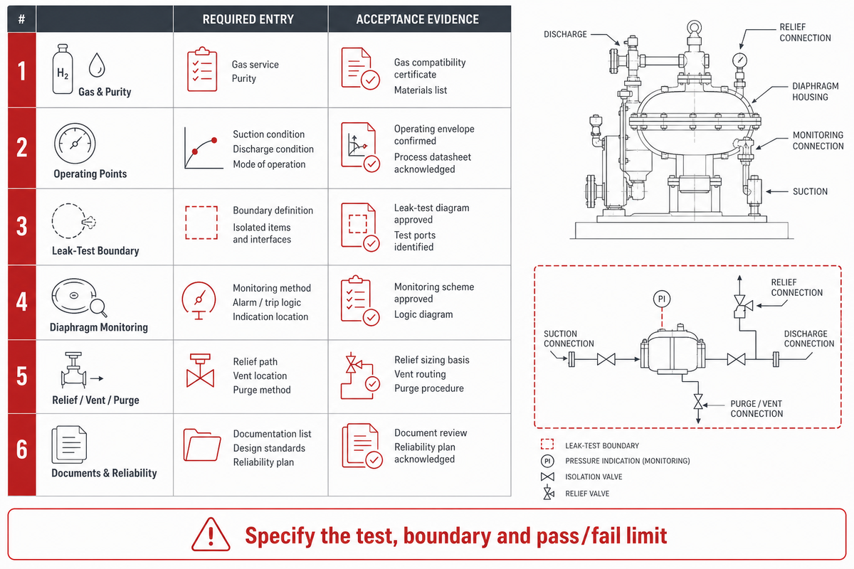
The Zero-Leak RFQ Acceptance Protocol converts a containment promise into named boundaries, methods, witnesses, records and pass/fail actions. It avoids inventing one universal leakage value. Project owners set the acceptance limit from the gas consequence, applicable code, end use and site policy.
Six-step selection sequence
- Classify the gas consequence. Record toxicity, flammability, corrosivity, environmental impact, product value and required purity.
- Define the complete pressure envelope. Give minimum/normal/maximum suction, normal/maximum discharge, temperature limits and transient cases.
- State flow and time behavior. Include normal and peak normalized flow, turndown, starts, filling profile, annual hours and future capacity.
- Verify compatibility and cleanliness. Review every wetted material, cleaning condition, purge medium and downstream purity requirement.
- Compare architectures and availability. Evaluate diaphragm, piston, screw, centrifugal or emerging alternatives using unit count, maintenance, redundancy, energy and downtime.
- Freeze acceptance evidence. Put performance, leakage, detector function, controls, certificates and document delivery into the order.
Zero-leak duty RFQ checklist—copy these fields into the enquiry and purchase order:
| Parameter | Required entry | Acceptance evidence |
|---|---|---|
| Gas and purity | Full composition, impurity limits, end-use standard and sampling point | Material list, cleaning record and agreed analysis |
| Operating points | Minimum/normal/maximum suction, discharge, flow and temperatures | Guaranteed performance table and test report at agreed points |
| Leak-test boundary | Tagged items included/excluded, test gas, pressure, hold time and limit | Witnessed factory report tied to serial number and marked drawing |
| Diaphragm monitoring | Alarm, trip, fault-health and reset logic for both monitored sides | Functional simulation proving alarm, shutdown and no-signal fault behavior |
| Relief, vent and purge | Set points, discharge destination, purge sequence and isolation philosophy | Piping and instrumentation diagram plus cause-and-effect test |
| Reliability | Duty cycle, maintenance interval, critical spares, redundancy and availability target | Maintenance plan, recommended spares and availability calculation basis |
| Documents | Applicable codes/editions, certificates, manuals, drawings and test records | Approved document register completed before shipment |
Never leave the leak criterion as “no visible leak” unless that’s genuinely the project requirement and test method. Define the instrument, sensitivity, test pressure, stabilization and hold period, temperature correction, boundary and disposition for a failed test. Require the supplier to state whether the same test will be repeated after site installation.
Finally, ask for a guaranteed point at the lowest credible suction pressure. Nominal-point performance can still miss the real filling time or production rate when suction falls. If operating availability matters, define whether one machine must carry the duty during maintenance, whether standby auto-start is required and which spares must be held on site.
Cross-reference the leak-monitoring acceptance logic with WO2022002326A1, and state which project standard governs site testing. For hydraulically powered remote packages, the hydraulic-driven compressor overview can help identify utility and control-interface questions, although the gas-end design must still be qualified separately.
PanGeng can review a duty sheet against its booster, reciprocating and diaphragm options. Useful enquiries contain the completed checklist above, not only a gas name and final pressure.
Frequently Asked Questions
What is a diaphragm compressor mainly used for?
Diaphragm compressors are mainly used where the gas must remain separated from lubricating oil and where leakage, contamination or product loss has a high consequence. Common examples include hydrogen, helium recovery, calibration and analytical gases, toxic or flammable process gases, and moderate-flow duties with a large compression ratio. This technology isn’t automatically best for every high-pressure job; flow, suction range, duty cycle and lifecycle cost still govern selection.
Why are diaphragm compressors used for hydrogen?
They’re used for hydrogen because the metallic diaphragm separates the process gas from the hydraulic drive, supporting a clean gas path and monitored containment. They can also suit high compression ratios at moderate flow. However, “hydrogen service” isn’t a complete specification. Electrolyzer boosting, storage filling, recovery and vehicle fuelling have different suction pressures, flow profiles, final pressures, purity requirements and availability targets.
Are diaphragm compressors completely leak-free?
No compressor package should be accepted as absolutely leak-free from a technology label alone. A diaphragm head can provide strong process isolation, but the package still contains valves, fittings, instruments, relief devices, purge connections and vents. Treat leak-free duty as a measurable project requirement: define the tested boundary, test gas, pressure, method, instrument sensitivity, acceptance limit and alarm/trip proof in the purchase order.
What is the maximum pressure of a diaphragm compressor?
There’s no universal maximum. It depends on head design, staging, suction pressure, gas, temperature and product line. Request a guaranteed point at your real minimum suction and required discharge pressure.
When should I choose a piston compressor instead?
Choose piston when flow, turndown or unit-count economics dominate and its leakage, wear and purity performance are acceptable.
References & Sources
- U.S. Department of Energy, Gaseous Hydrogen Compression
- ISO, ISO 19880-1:2020 official scope and lifecycle page
- Solovev et al. — Pre-formed metal membranes for diaphragm compressors, Manufacturing Review (2026)
- WO2022002326A1, Diaphragm compressor leakage monitoring disclosure
- Recent review of hydrogen compression technologies and station safety context
- Gasworld, Aquamarine underground hydrogen storage compressor project
// SYS-DOC: WHY I WRITE THIS
[01] About PanGeng
PanGeng is an industrial gas compressor manufacturer based in Bengbu, Anhui, China. Since 2009, we have focused on the design, R&D, production, and manufacturing of customized gas compressor systems for oilfield, chemical, energy, hydrogen, nitrogen, biogas, and industrial air applications.
[02] Our Expertise
We write compressor guides based on real manufacturing and engineering experience, including hydrogen compressors, nitrogen compressors, booster compressors, medium and high-pressure air compressors, oilfield nitrogen injection systems, biogas compressors, and OEM/ODM custom compressor solutions.
Our engineering team supports customers from application analysis and compressor selection to production, factory testing, commissioning, spare parts, and after-sales service.
[03] Why You Can Trust This Content
The technical information in our articles is based on PanGeng’s in-house compressor design and manufacturing experience, current product capabilities, and project support for industrial clients in global markets. Our goal is to help buyers understand compressor types, pressure ranges, gas requirements, customization options, and long-term operating costs before making a purchasing decision.
CONTACT PROFILE
AUTHORITATIVE SOURCE
NAME
PanGeng Engineering Team
BRAND
PanGeng
COUNTRY
China
MODEL
B2B / OEM & ODM
EMAIL
pg20090705@163.com
PHONE
0552-4958225
WEBSITE
pgcompress.com
Related Posts
Trending now

![Low Pressure Hydrogen Compressor Applications [Guide]](https://pgcompress.com/wp-content/uploads/2026/09/low-pressure-hydrogen-compressor-applications-blog-featured-150x150.png)