Get in Touch with Pangeng

N2 Feed Air Compressor Sizing: System Architecture, Pretreatment, and Site Derating Guide

Contents
show
Most commissioning failures of a nitrogen plant don’t happen when an engineer multiplies the nitrogen flow rate by the wrong air factor. They happen at the physical piping between the compressor discharge and the generator inlet. Treating n2 feed air compressor sizing as a single catalog lookup neglects the 15%-18% regeneration purge drawn by heatless desiccant dryers, the 0.5-1.0 bar (7-15 psi, measured in pounds per square inch) pressure loss across coalescing and carbon towers, and the barometric density drop that starves air systems during hot summer afternoons.
This compressor sizing guide will help you size an air compressor by evaluating the factors to consider across different pretreatment purge budgets, coupled thermal derating, and pressure-split decisions between the primary air package and downstream nitrogen boosters. If you wish to use our air compressor cfm calculator or the baseline seven-step air-factor worksheet, you can start with our foundation n2 feed air compressor sizing calculation worksheet. Use the engineering best practices below to confirm total air compressor capacity and lock your multi-vendor procurement specifications.
Key Engineering Takeaways for N2 Feed-Air Systems
- Reference conditions create a hidden 7.3% volumetric deficit because compressor package Free Air Delivery (FAD) rated under ISO 1217 (20°C,
1 bar(a)) is roughly 7.3% larger by volume than nitrogen generator capacities quoted in European normal cubic meters (Nm³/hat 0°C,1.01325 bar(a)) or liters per second. - Pretreatment consumes both pressure and flow, as meeting ISO 8573-1:2010 Class [1:2:1] purity often requires adding roughly 7%–18% gross flow for desiccant air dryers plus 0.5–1.0 bar (7–15 psi) for particulate, coalescing, and activated-carbon beds.
- Oil-flooded screw compressors require packed carbon towers because standard 0.01 µm coalescing elements capture liquid aerosols at 0.0008 ppm; hydrocarbon vapors pass through the elements. Inline cartridge carbon filters lack residence time, making a full activated-carbon pellet bed mandatory when using a lubricated compressor.
- Keeping primary feed air below
13 bar(g)lowers operational costs and total cost of ownership: because raising primary discharge pressure adds roughly 1% shaft power per 2 psi (0.14 bar) across the entire air stream, applications above13 bar(g)pair an8–10 bar(g)feed compressor with a downstream nitrogen booster.
Map the Feed-Air-to-Nitrogen Battery Limits Before Sizing
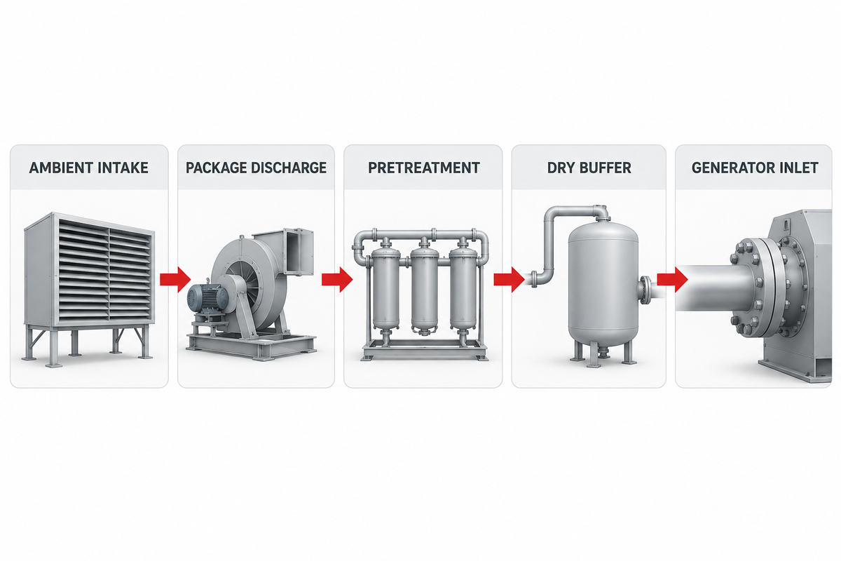
A reliable n2 feed air compressor sizing specification begins by identifying five physical battery limits from the ambient intake filter to the nitrogen generator inlet flange. Choosing the right air compressor and the right air compressor size requires knowing how much airflow is lost between components, because the required flow depends is on every valve and vessel in the train. When a buyer copies a single flow figure from a brochure and hands it to a compressed air sales professional, neither knows if dryer purge or filter differential pressure are included – leaving the plant with an undersized compressor and unplanned downtime.
In industrial air systems, compressor manufacturers rate package output at the discharge terminal under ISO 1217 Annex C (fixed speed) or Annex E (variable speed) reference conditions of 20°C (68°F), 1.0 bar(a) (14.5 psia), and roughly 0% relative humidity. Recall that cfm stands for cubic feet per minute; while north american sheets list scfm and psi, European nitrogen generator sheets express demand in Nm³/h referenced to 0°C (32°F) and 1.01325 bar(a). By the ideal gas law, 100 Nm³/h of dry gas at 0°C expands to 107.3 m³/h at 20°C and 1.0 bar(a). Failing to reconcile both sheets leaves the system roughly 7.3% short before ensuring the compressor meets peak demand.
Moreover, closed-loop compressor control and generator flow regulation, such as the oxygen-sensor feedback and flow-limiting orifice architecture disclosed in U.S. Patent US4725293A modulate inlet airflow and pressure dynamically to hold product purity under changing load. Meanwhile, the air purity arriving at that control valve must satisfy ISO 8573-1:2010 contaminant thresholds so moisture and hydrocarbons never reach the separation media. Defining the five battery limits in the table below separates what the compressor can deliver at its terminal from the net conditioned gas entering the separation beds.
| Battery Limit Point | Physical Location | Governing Standard / Basis | Typical Pressure & Thermal State | Flow & Loss Ownership |
|---|---|---|---|---|
| BL-1: Ambient Intake | Compressor air intake filter flange | Site barometric pressure, ambient °C, and relative humidity | 0.70–1.013 bar(a); -10°C to +45°C |
Baseline suction mass flow; subject to intake filter ΔP (25–50 mbar) and site altitude derating. |
| BL-2: Package Discharge | Aftercooler outlet / package terminal flange | ISO 1217 Annex C/E Free Air Delivery (FAD) | 7.5–13.5 bar(g); ambient + 8°C–15°C approach |
Gross compressor output (Q_gross); often 100% saturated with water vapor plus bulk condensate. |
| BL-3: Wet Receiver & Pretreatment | Wet air receiver, pre-filters, air dryer, and carbon tower | ISO 8573-1:2010 target purity class [1:2:1] or [1:4:1] |
0.5–1.0 bar (7–15 psi) cumulative ΔP across elements | Often consumes about 0.5%–2% drain loss (refrigerated) or roughly 7%–18% regeneration purge (desiccant). |
| BL-4: Dry Buffer & Flow Control | Dry process air receiver and pressure regulator / sonic nozzle | ASME Section VIII receiver code; sonic orifice sizing | 7.0–12.5 bar(g); stabilized 10°C–35°C |
Absorbs cyclic PSA equalization surges so peak draw does not exceed dryer velocity limits. |
| BL-5: Generator Inlet Flange | PSA skid inlet valve or membrane module header | OEM generator datasheet (Nm³/h or SCFM) |
Minimum 6.5–10.0 bar(g) (PSA) or 8.0–12.5 bar(g) (membrane) |
Net dry, oil-free feed air (Q_net_gen) available to produce specified nitrogen output. |
Size the ISO 8573-1 Pretreatment Train and Dryer Purge Allowance
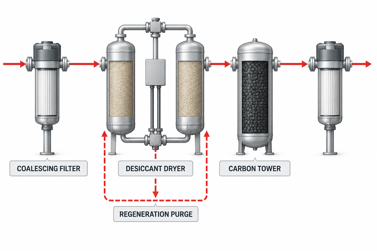
Once battery limits are fixed, the next step is building The Pretreatment-Adjusted Gross FAD Budget. Because the cfm required depends on downstream purification losses, every cubic meter of air leaving a compressor aftercooler is often 100% saturated with water vapor and carries lubricant aerosols, hydrocarbon vapors, and piping scale. Under ISO 8573-1:2010 Edition 3, compressed air purity is specified by three bracketed numbers [Particles : Water : Total Oil] and nitrogen generation skids often mandate either Class [1:4:1] (indoor PSA with a +3°C pressure dew point) or Class [1:2:1] (-40°C pressure dew point for cold-ambient piping, ultra-high-purity PSA, or hollow-fiber membranes).
Each purification stage imposes a parasitic flow and pressure tax that demands higher cfm from your compressor capacity. A refrigerated dryer consumes almost no compressed air (roughly 0.5%–1.5% across zero-loss or timed condensate drains) and adds 0.15–0.25 bar (2–3.5 psi) of pressure drop, but it can only chill air to a +3°C (37.4°F) pressure dew point. When specifications call for a -40°C (-40°F) dew point, a twin-tower heatless desiccant dryer often bleeds about 15%–18% of the compressed air stream back to atmosphere to regenerate its offline alumina or molecular sieve bed, while a heated blower-purge dryer still consumes roughly 7%–8% cooling purge during bed stripping.
One proven engineering alternative, originally detailed in U.S. Patent US4439213A couples a pressure-swing dryer directly to the PSA nitrogen towers so that dry, oxygen-enriched waste blowdown gas from the PSA vessels regenerates the upstream air dryer, eliminating dedicated compressed-air dryer purge while often using less than about 30% internal nitrogen purge. Where standard standalone dryers are used, however, the gross compressor flow rate (Q_gross) must follow the pretreatment budget equation:
The Pretreatment-Adjusted Gross FAD Budget Formula:
Where
Q_gross_FAD = (Q_N2 × AF_temp × K_ref) / [ (1 - f_purge - f_drain) × K_site ]Where
Q_N2 is required nitrogen flow, AF_temp is the temperature-corrected air factor, K_ref converts generator reference conditions to ISO 1217 (1.073 from 0°C to 20°C), f_purge is the desiccant dryer purge fraction (0.00 to 0.18), f_drain is condensate drain loss (0.005 to 0.015), and K_site is the altitude/ambient density factor.
| Pretreatment Train Architecture | ISO 8573-1:2010 Target Class | Particle & Oil Filtration Stages | Dryer Purge / Drain Flow Loss | Clean-to-Changeout Pressure Drop (ΔP) |
|---|---|---|---|---|
| Train A: Indoor Standard PSA (Refrigerated Dryer + Carbon Tower) |
Class [1 : 4 : 1](≤0.1 µm, +3°C PDP, ≤0.01 mg/m³ oil) |
Bulk water separator + 1.0 µm pre-filter + 0.01 µm coalescer + packed activated-carbon bed | Often 0.5%–1.5% (condensate drains only) |
0.35 bar clean → 0.75 bar (5–11 psi) at element changeout |
| Train B: High-Purity PSA / Cold Climate (Heatless Desiccant + Carbon Tower) |
Class [1 : 2 : 1](≤0.1 µm, -40°C PDP, ≤0.01 mg/m³ oil) |
1.0 µm & 0.01 µm coalescers + twin-tower heatless desiccant + activated-carbon tower + 1.0 µm dust after-filter | Often 15.0%–18.0% (continuous depressurization purge) |
0.50 bar clean → 1.00 bar (7–15 psi) at element changeout |
| Train C: Large Membrane / Energy-Saving Skid (Heated Blower-Purge Desiccant) |
Class [1 : 2 : 1](≤0.1 µm, -40°C PDP, ≤0.01 mg/m³ oil) |
Two-stage coalescing + external electric blower desiccant dryer + carbon tower + 0.01 µm polishing filter | Roughly 7.0%–8.0% (stripping & bed cooldown purge) |
0.45 bar clean → 0.90 bar (6.5–13 psi) at element changeout |
| Train D: PSA Waste-Gas Regenerated Dryer (Integrated Permeate Regeneration) |
Class [1 : 2 : 1](≤0.1 µm, -40°C PDP, ≤0.01 mg/m³ oil) |
Coalescing pre-filters + pressure-swing dryer regenerated by O₂-enriched PSA exhaust gas (US4439213A) | Nominal 0.5%–1.0% (zero extra feed-air dryer purge) |
0.40 bar clean → 0.80 bar (6–12 psi) across beds |
Why do carbon molecular sieve beds and membrane fibers fail even behind coalescing filters?
Compared to standard coalescing filters, both carbon molecular sieve (CMS) beds and polymeric membrane fibers fail for the same reason: Mechanical coalescers capture liquid oil droplets and aerosols, but hydrocarbon vapors pass through coalescing filters as a gas. As documented in industrial CMS poisoning investigations, oil and moisture molecules block the micropores of the carbon sieve, resulting in irreversible decay of purity, oil blowdown mufflers and black carbon dust at the exhaust of the PSA.
Even a high-efficiency 0.01 µm coalescing element that reduces liquid oil aerosol below 0.0008 ppm leaves residual oil vapor in the warm air stream. In addition, onsite nitrogen generation engineering primers emphasize that small thread-on cartridge activated-carbon filters are too small to protect a nitrogen generator: their short bed depth fails to provide the 2.5–4.0 second gas-contact residence time required to adsorb all hydrocarbon vapors. Whenever an oil-flooded compressor is used, a full-bed activated-carbon tower filled with pelletized carbon must be installed downstream of the dryer and coalescer.
Correct Sea-Level Compressor Ratings for Altitude, Ambient Heat, and Inlet Temperature
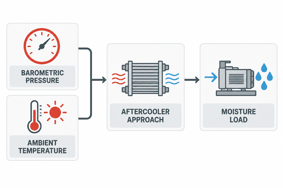
Selecting a compressor from a sea-level catalog table without site derating guarantees summer production bottlenecks. Because systems that separate nitrogen rely on molecular mass throughput rather than raw swept volume, altitude and ambient heat attack a feed-air train at three linked points: reduced intake air density at the compressor suction, higher discharge approach temperatures leaving the aftercooler, and elevated moisture and temperature correction factors inside the dryer and nitrogen generator.
First, as elevation increases, barometric pressure drops from 1.013 bar(a) (14.7 psia) at sea level to roughly 0.85 bar(a) at 1,500 m and 0.70 bar(a) (10.1 psia) at 3,000 m (10,000 ft). Although a positive-displacement rotary screw compressor inhales the same geometric cubic feet per minute of ambient air, the lower air density often reduces delivered mass flow (Nm³/h or scfm) by about 15%–30% at high altitude, as detailed in high-altitude compressor dimensioning guidelines. At the same time, thinner ambient air reduces fan cooling mass flow across air-cooled motors and oil coolers.
Second, intake temperature directly alters both power and dryer load. According to the U.S. Department of Energy Better Plants Compressed Air Cheat Sheet, roughly 80% of the electrical energy going into a compressor is converted into heat, and lowering compressor inlet air temperature by 10°F (5.6°C) often yields about a 2% energy savings. Conversely, when compressor room ambient temperature climbs to 40°C (104°F) and the air-cooled aftercooler operates at a 10°C approach temperature, compressed air enters the refrigerated dryer at 50°C (122°F) instead of the rated 35°C (95°F). That 15°C jump more than doubles the entrained water vapor load, overwhelming the dryer refrigerant circuit, raising pressure dew point above +10°C, and often cutting PSA carbon sieve capacity by an additional 8%–15%.
| Site Condition Scenario | Barometric Pressure & Ambient Temp | Intake Mass Flow Multiplier (vs. ISO 1217) | Aftercooler Outlet Temp (10°C Approach) | Dryer Moisture Load & Generator AF Penalty |
|---|---|---|---|---|
| Baseline Reference (ISO 1217) | 1.000 bar(a) at 20°C (68°F) |
1.000× (Catalog FAD baseline) |
30°C (86°F) | 1.00× moisture load; 1.00× generator air factor. |
| Hot Coastal Plant (Sea Level Summer) | 1.013 bar(a) at 40°C (104°F) |
0.936× (roughly -6.4% thermal density loss) |
50°C (122°F) | 2.45× water vapor load; requires oversized aftercooler/dryer plus 1.08×–1.12× PSA air factor. |
| High-Altitude Temperate Plant (1,500 m) | 0.846 bar(a) at 25°C (77°F) |
0.832× (roughly -16.8% combined derating) |
35°C (95°F) | 1.30× water vapor per unit mass; requires 1.20× gross compressor swept displacement. |
| High-Altitude Mining / Desert Site (3,000 m) | 0.701 bar(a) at 35°C (95°F) |
0.667× (roughly -33.3% combined derating) |
45°C (113°F) | 1.95× moisture per kg dry air; water-cooled aftercooler or chiller trim recommended. |
Match Pressure and Thermal Envelopes Across PSA and Membrane Architectures
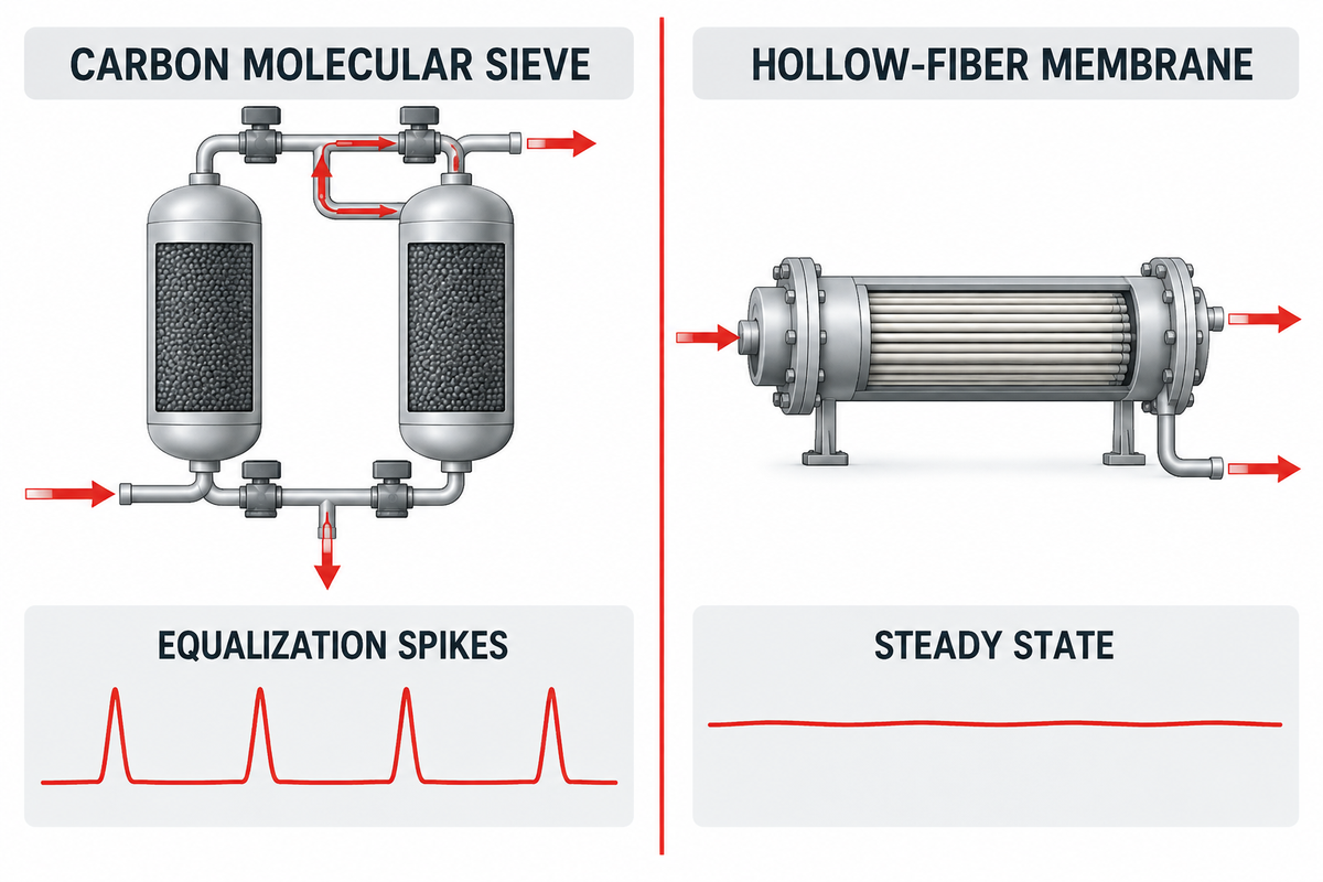
Not all nitrogen generators load a feed-air compressor the same way across various applications. Understanding air compressor duty differences between Pressure Swing Adsorption (PSA) carbon molecular sieve towers and hollow-fiber membrane separators is essential for choosing the right compressor pressure requirements and thermal control package, since each technology has distinct psi needs.
In a PSA system, compressed air cycles between two adsorber vessels packed with carbon molecular sieve. As explained in technical PSA adsorption analyses, CMS pores separate gas kinetically based on a 0.18 Å diameter difference, trapping oxygen molecules (3.46 Å) while allowing nitrogen molecules (3.64 Å) to pass through across an operating envelope of 4–13 bar (58–188 psig) and 10–25°C (50–77°F). Similarly, U.S. Patent US5711787A illustrates how pressure-swing separation cycles depend on maintaining tight feed pressure and temperature bands to avoid severe bed-size-factor (BSF) and recovery penalties. Because PSA towers switch every 45–90 seconds, the compressor sees a cyclic, pulsing flow demand.
By contrast, hollow-fiber membrane modules contain no moving cycle valves and draw a smooth, steady airflow. However, membrane permeation relies on Fick’s law partial-pressure driving force across polymer fiber walls (often 95%–99.5% purity). Membranes often require higher compressor discharge pressure, often 8.5–13.5 bar(g) (125–195 psig) to satisfy module psi needs, and incorporate an electric process heater at the skid inlet to hold feed air at 35–50°C (95–122°F), which raises fiber permeation capacity at the expense of slightly higher oxygen permeation. As practitioners note in Eng-Tips gas compression engineering discussions, when a membrane generator requires 145 psig (10 bar(g)) required pressure at the module inlet and pre-filtration drops 15 psi, the feed compressor must deliver a full 160 psig (11 bar(g)) at its discharge flange.
| Operating Parameter | PSA Carbon Molecular Sieve (CMS) System | Hollow-Fiber Membrane Separator | Impact on Feed-Air Compressor Selection |
|---|---|---|---|
| Economic Purity Window | Often 98.0% to 99.999% N₂ (10 ppm O₂) | Often 95.0% to 99.5% N₂ | PSA dominates high-purity electronics, laser, and chemical duties; membranes often suit 95%–99% blanketing and tire/pipeline purging. |
| Optimal Inlet Pressure Band | 6.5–10.0 bar(g) (95–145 psig); max 13 bar(g) |
8.0–13.5 bar(g) (115–195 psig); up to 15 bar(g) |
Membranes frequently require a 10–13 bar rotary screw stage to minimize fiber bundle count. |
| Optimal Feed Temperature | 10°C–25°C (50°F–77°F); performance drops >35°C |
35°C–50°C (95°F–122°F) via skid trim heater |
PSA demands low aftercooler approach temperature; membranes require liquid-free air entering an inline heater. |
| Flow Draw Profile | Cyclic with sharp 2×–3× equalization spikes |
Continuous, non-pulsing steady state | PSA requires dedicated wet and dry air receiver buffering; membranes require tight VSD pressure regulation. |
| Contaminant Sensitivity | Irreversible CMS poisoning from oil vapor or liquid water | Fiber plasticization from aromatics/oil vapor; swelling from liquid water | Both require ISO 8573-1:2010 Class 1 oil filtration and sub-ambient dew point margin. |
Decide Between Existing Plant-Air Tie-In and a Dedicated Feed-Air Skid
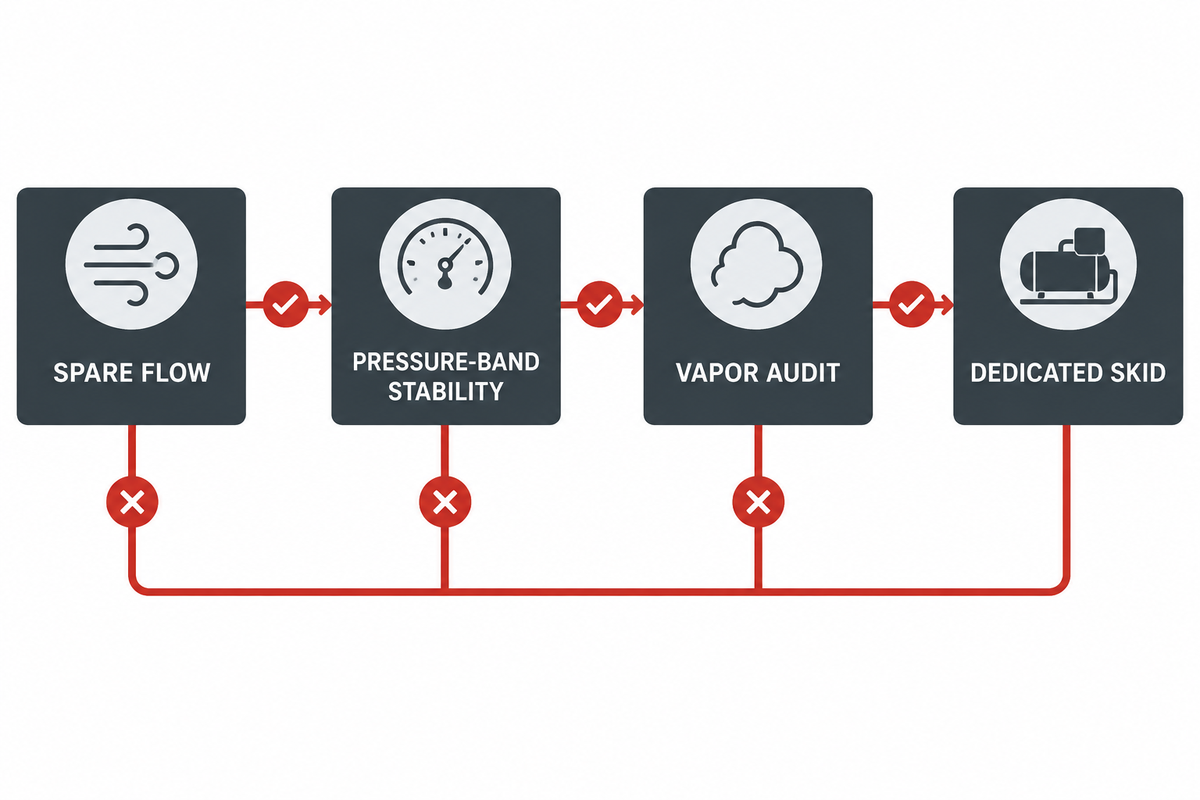
What do plant managers ask the most? Often, it’s whether they can connect an existing utility header instead of buying a dedicated compressor for a new nitrogen generator. With a general utility compressor for everyone in the shop where engineers just count the number of tools or applications, operating small tools, and assess how often and observe how long each tool runs, connecting a continuous 24/7 gas separation load to a header shared with pneumatic tools and machinery, often causes low-pressure alarms and purity trips.
First, audit real header losses. According to U.S. Department of Energy Compressed Air Tip Sheet #3, even a well-maintained industrial facility often loses about 5%–10% of total compressed air system flow to distribution air leaks, and unmaintained headers routinely lose roughly 20%–30%. Second, general factory headers are sized around intermittent air tool cfm requirements, where grinders, impact wrenches, or bagging cylinders often operate on a 15%–30% duty cycle, whereas a nitrogen generator draws a nominal 100% continuous base load of both cfm and psi. If pneumatic machinery causes header pressure to sag below 6.5 bar(g) (95 psig) for even 30 seconds, PSA bed velocity spikes and oxygen breaks through into the product tank. For broader plant utility comparisons, see our industrial air compressor systems engineering guide.
Tie-In vs. Dedicated Skid Decision Tree (4-Gate Engineering Audit)
- At Gate 1 (Verified 7-Day Spare Flow), does 7-day data logging prove that minimum header spare capacity exceeds
1.25 × Q_gross_FADduring peak production shifts, including a typical 5%–10% distribution leak allowance? If No → Specify a Dedicated Feed-Air Compressor Skid. - At Gate 2 (Pressure-Band Stability), does header pressure at the proposed tie-in branch stay above
P_gen_min + ΔP_pretreatment + 0.5 barat all times without dipping when large pneumatic tools or machinery cycle on? If No → Specify a Dedicated Feed-Air Compressor Skid (or isolate the generator behind an independent pressure-sustaining valve and buffer receiver). - At Gate 3 (Hydrocarbon & Silicone Vapor Audit) , is the plant header free from synthetic lubricant breakdown vapors, silicone mold-release aerosols, and/or intake exhaust fumes? Can you install a dedicated coalescing + packed activated-carbon tower at the nitrogen skid inlet? If No → A Dedicated Compressor Package with a ducted intake is warranted.
- At Gate 4 (Turn-Down & Operating Schedule Alignment) , does the nitrogen generator run 24/7 while the main factory air compressors shut down/unload on the weekends, requiring a 250 kW compressor to run at approx. 18% load to serve a 45 kW nitrogen skid? If Yes → A Dedicated VSD Rotary Screw Compressor is warranted.
Can an oil-flooded rotary screw compressor safely supply a nitrogen generator?
Yes, an oil-flooded rotary screw compressor can safely and efficiently provide a PSA or membrane nitrogen generator when combined with an engineered multi-stage filtration and activated-carbon tower train. A Class 0 oil-free compressor isn’t required for each installation as documented in compressed air requirement analyses for nitrogen generators.
In practice, an oil-injected screw compressor operating at 7.5–10 bar(g) delivers lower capital cost, higher volumetric efficiency, and longer airend bearing life than dry-screw alternatives, provided its discharge air temperature is cooled below 35°C before entering a 1.0 µm pre-filter, a 0.01 µm coalescing filter, a dryer, and a packed activated-carbon pellet vessel sized for ≤0.003 mg/m³ residual hydrocarbon content. Conversely, installing an oil-free compressor does not eliminate the need for filtration: ambient air in industrial zones routinely contains 1–5 mg/m³ of vehicle exhaust and solvent hydrocarbons that an oil-free compressor compresses and injects directly into the nitrogen generator unless an activated-carbon stage is retained.
Buffer PSA Bed-Switchover Pulses With Wet and Dry Receiver Staging
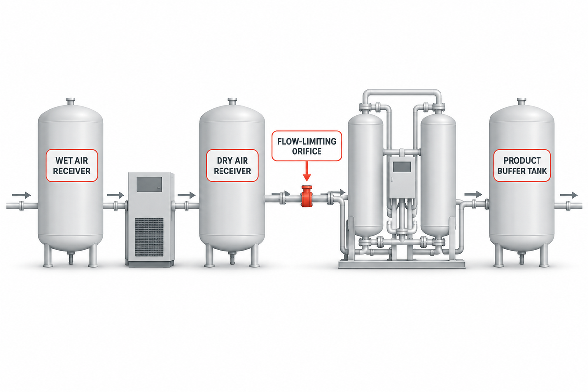
Sizing compressor flow rate without staging wet and dry air receivers sets up a destructive hydraulic tug-of-war between the compressor unloader, the air dryer, and the PSA cycle valves. Although a PSA nitrogen generator datasheet lists an average hourly or per-minute air consumption, its actual draw is highly non-linear: during the 2–5 second bed equalization and repressurization step, instantaneous air flow into the offline tower spikes to 2.5×–3.5× the nominal average flow rate.
As illustrated in the experimental pressure-swing cycle apparatus of U.S. Patent US5032150A, surge vessels are required to dampen cyclic pressure swings during blowdown, equalization and pressurization to allow the adsorption wavefront to traverse the bed uniformly. In plant-scale engineering (as chemical engineers describe in Cheresources process air receiver sizing discussions), splitting storage into a wet air receiver upstream of the dryer and a dry air receiver downstream of the purification train accomplishes two separate mechanical functions.
- In Stage 1 (Wet Air Receiver Between Aftercooler and Dryer), the vessel acts as a radiant heat dissipator, bulk condensate knockout drum (often removing about 60%–70% of condensed liquid water before the coalescing filters), and load/unload cycle buffer for the air compressor. Standard sizing rule:
3–5 gallons per SCFM(0.4–0.7 m³ perm³/minFAD). - In Stage 2 (Dry Air Receiver + Sonic Orifice Between Carbon Tower and PSA Skid), the vessel supplies the instantaneous high-flow gulp required during PSA bed switchover so the surge is drawn from stored dry air rather than pulled at triple velocity through the upstream desiccant dryer and carbon tower. Installing a flow-limiting orifice or control valve at the PSA inlet, as structured in U.S. Patent US4725293A caps peak repressurization velocity and prevents desiccant bed fluidization (“bed bumping”) and coalescer carryover. Standard sizing rule:
4–6 gallons per SCFMof average PSA feed flow, with the compressor load/unload pressure band set 0.8–1.2 bar (12–18 psi) above the PSA minimum regulated inlet pressure.
| Receiver Vessel & Position | Primary Engineering Function | Recommended Sizing Volume | Pressure-Band & Control Setting | Failure Mode if Omitted or Undersized |
|---|---|---|---|---|
| Wet Air Receiver (Compressor Outlet → Pre-Filter/Dryer) |
Cools saturated air, knocks out liquid water slugs, and prevents compressor short-cycling | V_wet ≥ (Q_FAD × t_cycle × P_atm) / ΔP_band(often 3–5 gal / SCFM) |
Fixed-speed Load/Unload: 0.7–1.0 bar band; VSD: PID target ±0.15 bar |
Rapid compressor load/unload cycling, oil-foam carryover, and flooded pre-filters. |
| Dry Process Air Receiver (Carbon Tower Outlet → PSA Inlet) |
Supplies instantaneous PSA bed repressurization gulp without accelerating dryer velocity | V_dry ≥ (Q_gulp × t_repress) / (P_rec - P_gen_min)(often 4–6 gal / SCFM) |
Operates at full line pressure upstream of skid pressure regulator & sonic orifice | Desiccant bead attrition, dew-point spikes, carbon dust migration, and PSA low-pressure trips. |
| Nitrogen Product Buffer Tank (PSA Outlet → Process Header) |
Smooths purity and pressure ripples during the 2–4 s PSA equalization pause | Sized for 60–180 seconds of process N₂ hold-up volume | Back-pressure regulator maintains constant downstream delivery psi | Downstream pressure droop and transient oxygen spikes during bed switchover. |
Split Compression Duty Between the Feed-Air Package and Downstream Nitrogen Boosters
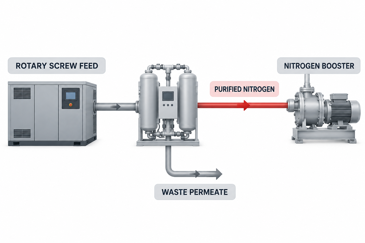
A critical capital and lifecycle energy decision The Feed-Air vs. Nitrogen-Booster Pressure Split Matrix arises whenever your application requires medium- or high-pressure nitrogen, such as 16–25 bar(g) chemical reactor inerting, 25–40 bar(g) fiber-laser cutting, or 150–300 bar(g) cylinder filling and accumulators. Should you specify a high-pressure feed-air compressor ahead of the nitrogen generator, or keep the feed-air compressor at standard plant pressure (7.5–10 bar(g)) and compress only the purified nitrogen product in a downstream booster?
Thermodynamics and separation physics heavily favor splitting the compression duty once delivery pressure exceeds 10–13 bar(g) (145–190 psig). First, according to the U.S. DOE Better Plants Compressed Air Cheat Sheet, raising compressor discharge pressure adds roughly 1% energy consumption for every 2 psig (0.14 bar) increase, and at fixed motor horsepower, a higher-pressure rotary screw stage delivers fewer cubic feet per minute of output. Second, as Plant Engineering’s analysis of compressed air boosters explains, compressing an entire primary air stream just to serve a high-pressure point of use wastes every kilowatt spent compressing gas that never reaches the process.
In a nitrogen generation system, that waste is magnified by the air factor (`AF`). To produce 100 Nm³/h of nominal 99.9% nitrogen at an air factor of 4.2:1, the feed-air compressor must compress 420 Nm³/h of air, of which 320 Nm³/h (roughly 76% of the total mass flow) is vented back to atmosphere at ~0.2 bar(g) as oxygen-rich waste permeate. Compressing all 420 Nm³/h of feed air to 25 bar(g) or 40 bar(g) means paying high-pressure shaft work on 320 Nm³/h of waste gas that’s immediately throttled and dumped, while also exceeding the 13 bar(g) structural vessel rating of standard PSA adsorbers. Instead, keeping the rotary-screw feed compressor at 8–10 bar(g) and routing only the 100 Nm³/h purified N₂ stream into dedicated oil-free nitrogen compressors (or selecting the proper reciprocating vs. diaphragm unit via our high-pressure nitrogen booster selection guide) slashes total connected horsepower and protects the separation skid.
| Target N₂ Delivery Pressure Band | Recommended Compression Architecture | Upstream Feed-Air Compressor Duty | Downstream N₂ Booster Duty | Primary Engineering & TCO Rationale |
|---|---|---|---|---|
| Band 1: Low-Pressure Process ( 5.0–8.5 bar(g) / 73–123 psig) |
Single-Stage Feed Air Only (No N₂ Booster Required) |
Standard rotary screw at 7.5–10.0 bar(g) discharge |
None (direct supply from N₂ buffer tank) | PSA/membrane inlet pressure directly satisfies downstream process header after 1.0–1.5 bar skid ΔP. |
| Band 2: Elevated Distribution ( 8.5–11.5 bar(g) / 123–167 psig) |
Medium-Pressure Rotary Screw Feed Air (No Booster if Skid Rated to 13 bar) |
Industrial 10.5–13.0 bar(g) rotary screw package |
None (verify PSA vessel code ≥13 bar(g)) |
Avoids a second machine while staying inside standard single-stage rotary screw and PSA valve envelopes. |
| Band 3: Laser Cutting & Autoclave ( 15–40 bar(g) / 218–580 psig) |
Split Architecture (Mandatory) (8–10 bar Feed Air + Oil-Free Reciprocating N₂ Booster) |
Standard 8.0–10.0 bar(g) rotary screw sized for Q_gross_FAD |
2-stage oil-free piston N₂ booster (5–7 bar(g) suction → 25–40 bar(g)) |
Compresses only the typical 20%–35% product N₂ fraction above 10 bar; avoids over-pressurizing PSA vessels and wasting energy on vented O₂ permeate. |
| Band 4: High-Pressure Cylinder / Accumulator ( 40–300 bar(g) / 580–4,350 psig) |
Split Architecture (Mandatory) (8–10 bar Feed Air + Multi-Stage Piston or Diaphragm Booster) |
Standard 8.0–10.0 bar(g) rotary screw + Class [1:2:1] pretreatment |
3- to 4-stage oil-free reciprocating or diaphragm N₂ compressor | Preserves 5–8 bar(g) suction density into the booster first stage, often cutting booster displacement and crankcase size by roughly 60%–80% vs. atmospheric suction. |
Illustrative Worked Shaft-Power Comparison (Explicitly Hypothetical Engineering Example):
Consider a laser-cutting and vessel-inerting line requiring 100 Nm³/h (63 SCFM) of nitrogen across two nominal purity cases (roughly 99.5% at
• Case A, Hypothetical Whole-Stream High-Pressure Air Compression (nominal 99.9% N₂ at
• Case B, Split Feed-Air + Nitrogen Booster Architecture (nominal 99.9% N₂ at
• Case C, High-Pressure
Consider a laser-cutting and vessel-inerting line requiring 100 Nm³/h (63 SCFM) of nitrogen across two nominal purity cases (roughly 99.5% at
AF = 3.2 vs. 99.9% at AF = 4.2) and two delivery pressures (25 bar(g) vs. 150 bar(g)), including a typical 10% combined dryer/reference allowance:• Case A, Hypothetical Whole-Stream High-Pressure Air Compression (nominal 99.9% N₂ at
25 bar(g)): Compressing all 462 Nm³/h of gross feed air from atmospheric pressure to 27 bar(g) in a multi-stage air package requires roughly 78 kW of shaft power, yet 362 Nm³/h of that 27 bar gas is throttled and vented as waste oxygen permeate.• Case B, Split Feed-Air + Nitrogen Booster Architecture (nominal 99.9% N₂ at
25 bar(g)): Compressing 462 Nm³/h of gross feed air to 8.5 bar(g) in a rotary screw requires ~46 kW, and boosting only the purified 100 Nm³/h nitrogen product from 6.5 bar(g) suction to 25 bar(g) in an oil-free reciprocating N₂ booster requires ~6.5 kW a combined total of 52.5 kW (an illustrative 25.5 kW or roughly 32.7% shaft-power reduction, saving over 200,000 kWh/year at 8,000 h/yr operation).• Case C, High-Pressure
150 bar(g) Delivery (nominal 99.5% N₂, 352 Nm³/h gross feed air): The 8.5 bar(g) rotary screw feed compressor draws ~35 kW while the multi-stage N₂ booster (6.5 bar(g) → 150 bar(g) on 100 Nm³/h N₂) draws ~18.5 kW (53.5 kW total), whereas compressing all 352 Nm³/h of air to 150 bar would exceed 118 kW and violate standard PSA adsorber pressure ratings.
Specify Multi-Vendor RFQ Battery Limits Without Scope Gaps
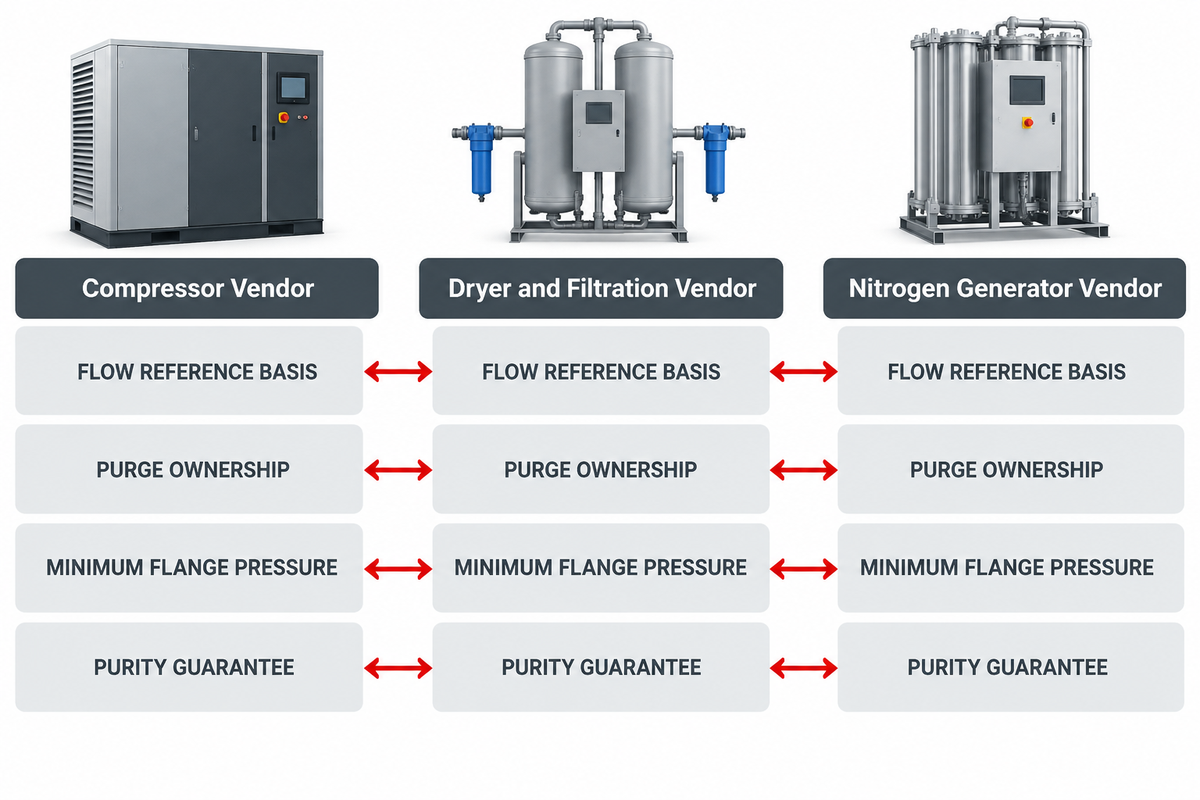
When procurement teams purchase the rotary-screw air compressor from Vendor A, the desiccant dryer and carbon tower from Vendor B, and the PSA nitrogen skid from Vendor C, minor differences in datasheet conventions routinely compound into a typical 15%–25% capacity shortfall. Even high-efficiency PSA cycles—such as the integrated dryer-regeneration design in Patent CA1201663A achieving yields above roughly 25% at about 99.5% nitrogen-plus-argon purity (60 volumes of product per volume of adsorbent per hour)—will fail factory acceptance if the upstream air package delivers less mass flow or lower flange pressure than the adsorber valves require.
During commissioning, this finger-pointing issue is addressed by requiring each of the vendor’s responses to our Request for Quotation (RFQ) to incorporate the 8-point interface schedule. In the absence of the 8-point interface schedule, vendor responsibility for a single package in the integrated system may be defined using our Gas Compressor Package RFQ Scope documentation.
| RFQ Interface Item | Compressor Vendor Datasheet Requirement | Dryer & Filtration Vendor Requirement | N₂ Generator / Booster Vendor Requirement |
|---|---|---|---|
| 1. Flow Reference Basis | Quote terminal Free Air Delivery (FAD) per ISO 1217 Annex C/E at actual site elevation and peak summer °C. | Rate dryer inlet capacity at minimum operating pressure and maximum aftercooler outlet temperature. | State required inlet air in both Nm³/h (0°C, 1.013 bar(a)) and equivalent ISO 1217 FAD (20°C, 1 bar(a)). |
| 2. Pretreatment Purge Ownership | Include f_purge (often 7%–18% for desiccant) and f_drain (roughly 1%–2%) inside gross compressor FAD. |
Guarantee maximum regeneration purge percentage across full turndown or dew-point demand control. | Confirm whether internal PSA blowdown gas regenerates the dryer (CA1201663A) or requires dry feed air. |
| 3. Minimum Flange Pressure | Set full-load discharge pressure ≥ P_gen_min + ΔP_dirty_filters + 0.5 bar line allowance. |
State maximum dirty-element ΔP across pre-filters, dryer bed, carbon tower, and dust after-filter. | Specify minimum allowable dynamic pressure at the PSA/membrane inlet flange during bed switchover. |
| 4. Unload / VSD Pressure Band | Lock fixed-speed unload cutout or VSD target band within design working pressure of all downstream vessels. | Verify vessel MAWP exceeds compressor safety relief valve set point. | Supply inlet pressure regulator to hold constant feed pressure into the separation beds. |
| 5. ISO 8573-1:2010 Purity Guarantee | Declare baseline oil carryover (mg/m³) at package discharge flange. |
Guarantee outlet purity per ISO 8573-1:2010 Class [1:2:1] or [1:4:1] with packed carbon tower residence time ≥3.0 s. |
State maximum allowable particle size, pressure dew point, and total oil (aerosol + vapor) for CMS warranty. |
| 6. Thermal Approach & Trim | Guarantee aftercooler approach temperature ≤10°C above peak ambient at site elevation. | Apply inlet temperature correction factor to dryer sizing at peak summer aftercooler discharge °C. | Provide skid inlet temperature sensor and high-temp alarm (PSA) or thermostatic trim heater (membrane). |
| 7. Wet/Dry Receiver & Sonic Nozzle | Approve wet receiver volume for load/unload cycle frequency limits (starts per hour). | Place wet receiver ahead of pre-filters and dry receiver downstream of carbon dust filter. | Supply calibrated sonic flow-limiting orifice at PSA inlet to prevent bed over-velocity during startup/equalization. |
| 8. Witness Test & Telemetry | Provide ISO 1217 shop test certificate and specific power (kW / 100 cfm) curve. |
Include online dew-point transmitter (-80°C to +20°C) and differential pressure gauges. |
Interlock N₂ product oxygen analyzer with feed-air low-pressure and high-dew-point trip relays. |
Frequently asked questions
How do we size the required compressors and air receiver and control outlet pressure?
Start by multiplying required nitrogen flow by the temperature-corrected generator air factor, then divide by the net delivery fraction after subtracting desiccant dryer purge (often 7%–18%) and site altitude/temperature derating. A wet air receiver (3-5 gal/SCFM) is staged before the dryer, a dry receiver (4-6 gal/SCFM) is staged before the PSA skid, and compressor load pressure is set to 0.8-1.0 bar above the generator regulator setpoint.
What is the difference between CFM and SCFM when matching a compressor to a nitrogen generator?
In compressor selection, CFM (or ISO 1217 Free Air Delivery, ACFM) indicates the volume of air the compressor delivers referenced to actual intake temperature, pressure, and humidity, whereas SCFM (or Nm³/h) measures gas mass flow at fixed standard reference conditions (such as 60°F and 14.696 psia, or 0°C and 1.013 bar(a)). Always convert both data sheets to the same thermodynamic reference state before sizing.
Is it better to oversize an air compressor for a nitrogen generation plant?
A modest engineering margin (often 10%–15% above calculated gross peak flow) protects against filter fouling and ambient heat, but grossly oversizing a fixed-speed rotary screw compressor forces rapid load/unload compressor cycles, elevated sump moisture, and high unloaded power waste. Instead of oversizing by roughly 50%, account for other variables such as dryer purge and altitude, and use variable speed drive (VSD) trim control.
Does higher discharge PSI reduce the CFM a rotary screw compressor delivers?
Yes. For a fixed motor kilowatt rating, selecting a higher-pressure airend gearset (for example, 13 bar(g) / 190 psig instead of 8 bar(g) / 115 psig) increases the internal work of compression per unit mass and slightly increases internal slip, often reducing the volume of air the compressor can deliver by roughly 12%–22% while raising specific energy consumption by about 1% per 2 psi.
Does a bigger air receiver tank give a nitrogen generator more continuous CFM?
A larger wet or dry air receiver stores compressed gas to absorb short 2 to 5 second surges (PSA bed re-pressurization cycles) and helps slow down the load/unload cycling of the compressor, refilling the tank. However, if the average continuous air consumption of the nitrogen generator exceeds the site-derated Free Air Delivery of the compressor, header pressure will continue to decrease regardless of the volume of air receiver tank.
Which compressor type is best for continuous 24/7 nitrogen generation duty?
Industrial rotary screw compressors (either oil-injected with a packed activated-carbon tower or Class 0 oil-free two-stage screw) are the primary selection criterion for continuous 24/7 feed-air duty because they’re engineered for a nominal 100% duty cycle with low vibration. Reciprocating piston compressors are reserved for small intermittent skids or for downstream high pressure nitrogen booster stages (20-300 bar).
When should you add a nitrogen booster compressor instead of raising feed-air pressure?
Add a downstream nitrogen booster whenever your process requires nitrogen above the normal 7–10 bar(g) PSA or 8–13 bar(g) membrane operating window. Because roughly 65%–85% of the feed air is vented at atmospheric pressure as oxygen-rich waste permeate, compressing the entire feed-air stream above 13 bar(g) wastes substantial electrical power compared with boosting only the purified nitrogen stream.
References & Sources
- International Organization for Standardization (ISO). ISO 8573-1:2010, Compressed air, Part 1: Contaminants and purity classes (Edition 3, confirmed current).
- U.S. Department of Energy (DOE), Industrial Technologies Program. Energy Tips: Compressed Air Tip Sheet #3 – Minimizing Compressed Air System Pressure.
- U.S. Department of Energy (DOE), Better Buildings/Better Plants Solution Center. Compressed Air System Cheat Sheet, Energy Treasure Hunt Rules of Thumb.
- Frey, B., Haynie, M., & Psaras, J. U.S. Patent US4439213A, Nitrogen Generation System with Pressure Swing Dryer Regeneration (and corresponding family Patent CA1201663A).
- Emanuel, G. et al. U.S. Patent US4725293A, Nitrogen Gas Generator Feed-Air Flow Control System.
- Kumar, R. et al. U.S. Patent US5032150A, Pressure Swing Adsorption Cycle and Surge Equalization.
- Smolarek, J. et al. U.S. Patent US5711787A, Pressure Swing Adsorption Process Feed Air Pressure and Temperature Parameters.
- Atlas Copco Compressed Air Wiki. PSA Nitrogen Generator: How Pressure Swing Adsorption Works & Dimensioning Compressor Installations at High Altitudes.
- Holtec Gas Systems. See Onsite Nitrogen Generation Technology Comparison & Activated Carbon Bed Primer.
- Plant Engineering. See Advancing Efficiency and Performance with Compressed Air Boosters in Modern Plants.
// SYS-DOC: WHY I WRITE THIS
[01] About PanGeng
PanGeng is an industrial gas compressor manufacturer based in Bengbu, Anhui, China. Since 2009, we have focused on the design, R&D, production, and manufacturing of customized gas compressor systems for oilfield, chemical, energy, hydrogen, nitrogen, biogas, and industrial air applications.
[02] Our Expertise
We write compressor guides based on real manufacturing and engineering experience, including hydrogen compressors, nitrogen compressors, booster compressors, medium and high-pressure air compressors, oilfield nitrogen injection systems, biogas compressors, and OEM/ODM custom compressor solutions.
Our engineering team supports customers from application analysis and compressor selection to production, factory testing, commissioning, spare parts, and after-sales service.
[03] Why You Can Trust This Content
The technical information in our articles is based on PanGeng’s in-house compressor design and manufacturing experience, current product capabilities, and project support for industrial clients in global markets. Our goal is to help buyers understand compressor types, pressure ranges, gas requirements, customization options, and long-term operating costs before making a purchasing decision.
CONTACT PROFILE
AUTHORITATIVE SOURCE
NAME
PanGeng Engineering Team
BRAND
PanGeng
COUNTRY
China
MODEL
B2B / OEM & ODM
EMAIL
pg20090705@163.com
PHONE
0552-4958225
WEBSITE
pgcompress.com